Eng-Tips is the largest engineering community on the Internet

Intelligent Work Forums for Engineering Professionals

Concrete Column Above a Steel Beam with no support bellow?

Status
Not open for further replies.

EdgarPeriera

Civil/Environmental
Jan 13, 2024
13
0
0
PT
Good Morning all,

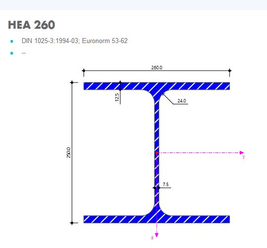
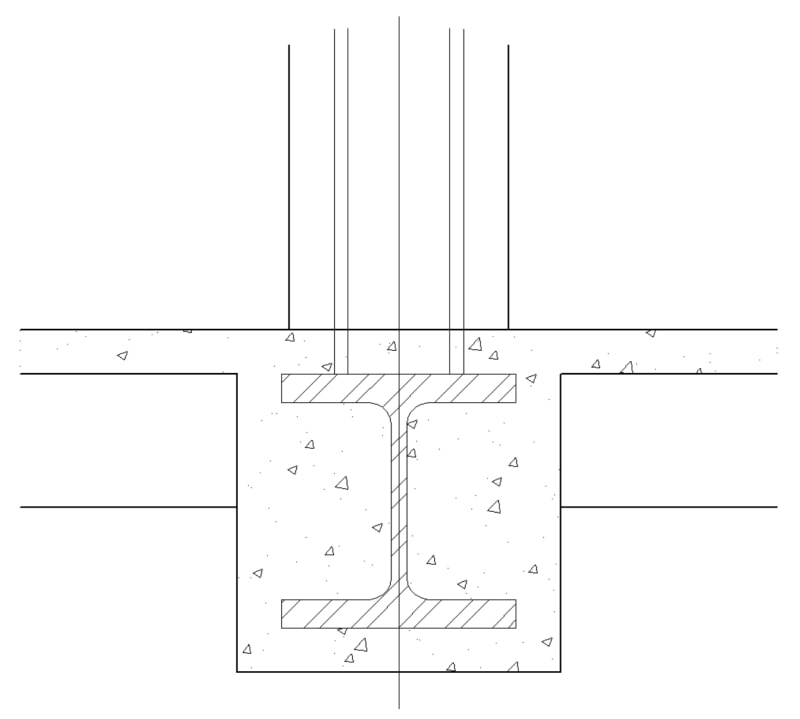
Please help me with the image bellow. The engineer Is proposing a steel column HEA260 at "Pórtico4". The Columns P5, P6, P7, P23, P24 and P9 are ALL CR columns with 250x250mm. As a constructer I have a great deal of difficulty accepting this solution but the engineer was quite insulting and said that there is no problem with this solution. I requested construction details that he didn't provide so far. I do not like to question the technical knowledge of the engineering but I've never done or seen something like that in 20 years of construction. My particular concern is with the columns P23 and P24 with no support underneath and the connection of the steel beam to the edge columns P5 and P9. This beam is at the second floor residential area with a flat concrete roof above. Could someone help me clarify this problem and probably elaborate a response to the engineer? Thank you very much for all your help.

Capture_cbxqhm.jpg
 
Replies continue below

Recommended for you

Just to clarify, my main issue is not in having two floating columns mid span of the beam. My main issue is that those columns are RC columns on top of a steel beam. It looks like an odd hybrid solution that could be avoided...
 
There is a reason he’s introducing steel into a concrete building. Possibly a ceiling height issue and a concrete transfer girder was just too deep for the architect to tolerate.
From a structural perspective, there is nothing wrong with having columns above a girder, but not below. Transfer girders are common, especially with changing column grids apt when a large open space is needed down low in a building.
I also see no issue with having a concrete column over a steel beam, provided it’s all sized and detailed properly. I’m guessing he will have rebar welded to the top flange as starter bars for the columns and have the beam adequately braced for the point loads.
 
I believe that all that makes sense. Indeed the focal reason is the ceiling height. But the way he draws the steel beam not anchored to the columns or concrete wall. It interrupts the rc columns and new columns start from there. In theory all makes sense, but I've never seen a real world case where this solution is applied. And I've searched all over the internet and not a single photo or a construction detail with that same scenario. And that made worry about the solution.
 
You last message makes it seem like you're concerned at locations where there is a concrete column above and below the beam at the same spot where it appears the current design has the beam framing continuous through and the column stopping and starting, can you confirm?

If so, I agree with your concerns. Those would normally be done with continuous columns and cast in or bolted on weld plates for the beams to frame into.
 
@Jayrod12 yes that's one of my concerns. Continuous columns make greater sense. Have you ever seen a real world example similar with the solution presented? Is it feasable?
 
Has the engineer indicated that he is not going to provide you with any more details? If not, I'd wait to see what the actual details are. While some of this is a little different, it's feasible. I wouldn't be surprised if they intended for the beams to be continuous and cast into continuous columns if the dimensions work.

If you have concerns after the design is finalized and all details are provided, you can provide a detailed description of your concerns in writing to then engineer and the owner and give the engineer an opportunity to answer those concerns. If they do not, you or the owner can then hire a third party engineer to review the design and determine whether or not is satisfactory. Note that the third party reviewer would need strict instructions not to consider differences of opinion/style, but only identification of conditions that are objectively unsafe or unreliable.


@EdgarPeriera ,

Can you post the upper floor plan ? Is this bldg. at high seismic zone ?
I think the 1st floor plan slab system , one way hollow core slab. Is this true ?
Just visual check , HEA260 steel beam spanning 9 m is not suitable . Even if the beam designed as composite with topping .

Why the upper columns are also not steel ? Or can the subject columns ( columns P23 and P24 ) be deleted ?

Use it up, wear it out;
Make it do, or do without.

NEW ENGLAND MAXIM


Edgar, your wrath should probably be directed to architect and owner for this building layout...leading to solution above.
25/25cm is not much of a column to connect 9m long hea260 to...so continuoous beam could be an option.
 
Is there a concrete slab cast over the HE beams? How are the columns connected? Dowels into the slab or dowels welded to the HE beams. Unless I'm missing something, I don't see a problem except maybe at P23 and P24 (I thought there was a beam... maybe joists) where there may not be enough lateral support, except as provided by the 'joists?'. At the other columns there appears to be adequate torsional restraint offered by the connecting beam. A bit of a problem, if a slab, might the proper column placing location of the columns above.

-----*****-----
So strange to see the singularity approaching while the entire planet is rapidly turning into a hellscape. -John Coates

-Dik
 
@dik the He beam is encased on a ribbed slab. Those are not joists. About the connections I don't know. I'm still way ting for the details to bring some light into this...
 
If those are ribs... then I'd be less concerned about the stability of the beam column supports. Is the ribbed slab 50mm thick with the 'beam/joist' component 150mm?

As far as details go, I'd just weld rebar dowels to the steel beam, and extend them into the column. This is not tricky construction.

-----*****-----
So strange to see the singularity approaching while the entire planet is rapidly turning into a hellscape. -John Coates

-Dik
 
Something like... I used a 260M... I guess it's different...

Clipboard01_ufxlvv.jpg


Clipboard01_hajdlc.jpg


-----*****-----
So strange to see the singularity approaching while the entire planet is rapidly turning into a hellscape. -John Coates

-Dik
 

not at all, done this with concrete often occasionally. There isn't enough concrete thickness to develop a hook...<Sarky> Might consider tapping threading the rebar and bolting it through the beam? </Sarky> [ponder]

-----*****-----
So strange to see the singularity approaching while the entire planet is rapidly turning into a hellscape. -John Coates

-Dik
 
Is the beam to be encased in concrete as dik shows?? Depth to span ratio is 34.6; hopefully the column loads are not too big; looks like a large uplift at Column P6.
 
just a WAG...

-----*****-----
So strange to see the singularity approaching while the entire planet is rapidly turning into a hellscape. -John Coates

-Dik
 
Status
Not open for further replies.
Back
Top