Continue to Site

Eng-Tips is the largest engineering community on the Internet

Intelligent Work Forums for Engineering Professionals

  • Congratulations IDS on being selected by the Eng-Tips community for having the most helpful posts in the forums last week. Way to Go!

Concrete Jacket - Dowel Spacing - No Shear Flow?

Status
Not open for further replies.

Redacted

Structural
Mar 12, 2016
160
Hi there, I am going over a past problem and would like some clarity.

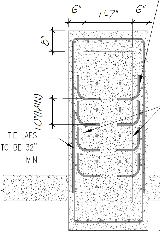
I recently designed a concrete jacket.

To simplify the problem. The top of an existing column was in poor condition. I have a lateral load applied to the column at the top (cantilever). I want to provide a transfer mechanism to transfer this load at the top to some of the sound concrete below. I want to figure out how to determine the spacing of the shear dowels I need to transfer the load.

See below (the blue square around the black square is the RC jacket)

engtips_shear_dowel_spacing_lrs282.png


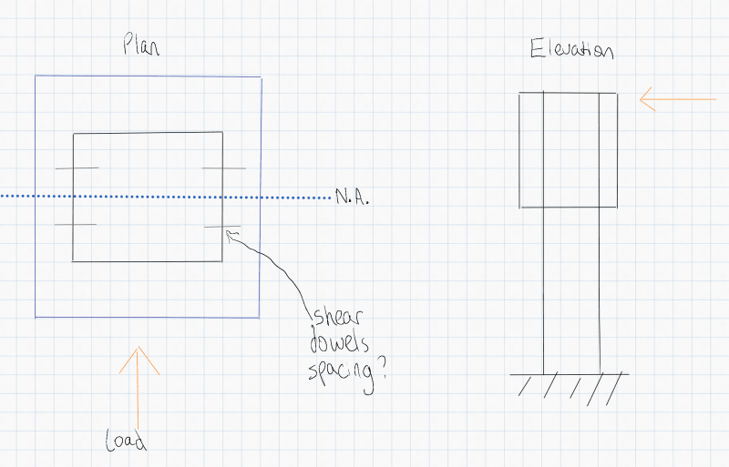
The issue that I am realising is that because the neutral axis of the concrete jacket is the same as the neutral axis of the existing concrete, there wouldn’t be any shear flow in that location. So I don't think that I can calculate it like a normal shear flow problem.

I was looking into what was done for flitch beams as it seems like a similar problem and there wasn’t much guidance on the spacing when you have a concentrated load (it’s quite straightforward for a UDL), one document I was reading was pretty much saying try to have the dowels as close to the concentrated load as possible. Although this doesn't tell me much about the spacing.

I know the number of dowels required to take the load (18) but can’t have them all congested at the exact location of the load as there would be too many.
Does anyone have any advice or guidance for situations like this?

On a side note… Do you know of any good books or resources that discuss and provide concrete jacket design examples?

The only resources I can find are university research papers that only focus on one element of RC jacket design, which isn’t very helpful from a practical design point of view.
 
Replies continue below

Recommended for you

1) there probably will be shear flow if you consider the concrete section to be flexurally cracked.

2) If your strategy is to truly bypass the upper concrete, you can probably transmit the shear and moment to the concrete below by conceptualizing your wrap as a pair of opposing u-straps. Under that model, the demand in the anchors would be pretty nominal.
 
The purpose of the dowels is simply to connect the two concrete sections. The are only there to mimic the interstitial bond that would occur within the concrete matrix when all is placed together.

 
@KootK

To provide some more clarity, the damaged portion at the top of the existing column will be removed and a new portion poured. The new portion will be connected to the existing with vertical dowels and an RC jacket will be merged with this. The total height of the repair will be about 8'. With the top 4' being new concrete doweled into the existing and the bottom 4' being the new RC jacket around the existing. The reinforcement will be continuous between the jacket and new concrete at the top (apart from the side dowels into the existing, these would just be on the bottom 4').

The cross-section shown below may be able to clarify what I stated above a bit better and will show what my thoughts are for the repair.

eng_tips_rc_jacket_pjst96.png


My thoughts for the repair as a whole is that jacket will confine the system. With the confinement preventing concrete breakout etc. When you say u straps, do you mean like the ties I have shown? Would you be able to elaborate a bit more on the u-strap model? I think understanding this would be helpful as the jacket confinement reinforcement used was based on the recommended minimums (T12's at 10" ties, and enough vertical bars to satisfy 0.8% of the jacket area).

@Ron yes that is true but to mimic this monolithic shear interface, I would still need to know how many dowels are needed to achieve this. Normally I would think that it is done by shear flow calculations. I have specified surface roughening to be done before pouring the RC jacket, which will also improve the monolithic behaviour but I didn't want to just rely solely on this because I don't know how to quantify if a roughened surface alone would be enough to achieve monolithic behaviour? This is why I was also looking to include the side dowels.
 
1) I did a poor job of reading your initial post and, originally, thought that we were discussing a steel jacket. That said, I feel that my original comments still apply.

2) Based on what you've told us to date, I don't feel that you need the jacket. Confinement approaches are usually used for members with heavy axial loads or flexural demands that will take the member into the elastic range. Your situation doesn't sound like either of those conditions.

3) As far as shear flow and dowels go, I feel that your best analog will be the ACI 318 provisions that deal with adding second pour, composite toppings to concrete beams. The principles involved are nearly identical to what you're seeking to do. Realistically though, I don't feel that composite flexural behavior is a reasonable goal to strive for given your proportions on this thing. The flexural stresses may not have sufficient "time & space" over which to rearrange themselves in that fashion.

OP said:
Would you be able to elaborate a bit more on the u-strap model?

4) In the world of street lamp posts, sometimes a flexural splice is made by sleeving a larger diameter, tapered pipe section over top of a smaller diameter one. Imagine the likely design model for that connection and then extend it to your situation.

OP said:
I think understanding this would be helpful as the jacket confinement reinforcement used was based on the recommended minimums (T12's at 10" ties, and enough vertical bars to satisfy 0.8% of the jacket area).

Where have you gotten those minimums from?

 
Hi KootK

2)Yes you are correct, the axial compression loads in the column are negligible. The main load is a concentrated lateral load at the tip of the column, which is ~ 1000kN. Essentially I just want to make sure this load can transfer down from the tip (as in preventing the tip from breaking off).

As the concrete currently at the tip has a crack (it probably lasted about 100 years), the tip will be replaced with new concrete.

Initially, I was thinking of just having the vertical dowels connect the newly poured concrete tip to the existing column. I considered the dowels in two ways. The first approach was with shear friction, which worked well from a calculation point of view, but shear friction requires the rebar to be fully developed on both sides. For a 25mm bar, that would be approximately 50*25= 1250mm =~4', which to my knowledge isn't possible to do with post-installed rebar. I have specified that the vertical bars be embedded 2' into the existing concrete. As I couldn't solely rely on shear friction, due to the development length, I also considered them as anchors. I believe the only way that can work is if the concrete is confined to prevent concrete break out failure? The additional benefit of the concrete jacket is that it increases the edge distances/shear capacity of the top of the concrete. If I was to consider concrete breakout etc, the HILTI tables load reduction factors would make the shear capacity of each anchor too small.

3) Based on the needs, I think it's more of a composite shear behaviour that is required. I just need to reinforce the top tip of the column to take the concentrated load in shear.

4)Initially I was considering the column minimum reinforcement stipulated in the Eurocode 2 (EC2)

EC2_Column_Minimum_Reinforcement_khcss2.png


However, 0.2% seemed quite light, so I took a look to try to find some examples specific to reinforced concrete jacketing. I found a research paper in the IOSR Journal of Mechanical and Civil Engineering that recommended 0.8%, which seemed like a decent middle ground to what the EC2 has, so I went with that. Due to the size of the column, the area of steel requirements can get quite high very quickly.
 
Status
Not open for further replies.

Part and Inventory Search

Sponsor