Hi all,
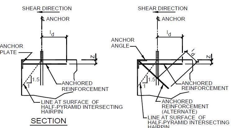
I am working on a project where I received some column loading from a prefabricated metal building supplier, and I just need to design the building foundation system. Due to the client requesting no interior columns for a 75'-0" clear span, the loading coming in from these columns is significant. I am getting a factored shear force of 86.6 kips from these columns, which is acting away from the building structure. The immediate issue was getting the anchorage to work, so we looked into providing supplemental anchorage reinforcing for shear per ACI D.6.2.9, however, the pier is elevated from the building floor slab (see attached section and plan view), so it was starting to become a bit of a mess trying to transfer the shear from the anchors to the anchor reinforcing to the hairpin reinforcing to the slab and the required pier dimensions were getting a bit ridiculous.
My coworker suggested the idea of embedding a wide flange member into the pier with a welded plate on top that would be flush with the top of concrete. The building column anchors would then bolt to the plate/wide flange and we would have hairpins wrapped around the wide flange to transfer the shear into the floor slab (also shown in attachment). We discussed needing to check the beam for shear and moment and to ensure the slab could handle the loading.
I just thought I would put this out there to get any feedback on the proposed beam embed as this would seem to be the easier, more cost-effective option of transferring the shear. Or to open it up to other suggestions on ways to do this.
Thank you!

