Continue to Site

Eng-Tips is the largest engineering community on the Internet

Intelligent Work Forums for Engineering Professionals

  • Congratulations cowski on being selected by the Eng-Tips community for having the most helpful posts in the forums last week. Way to Go!

Concrete stiffness in slab design at Ultimate Limit State

Status
Not open for further replies.
Jan 14, 2022
2
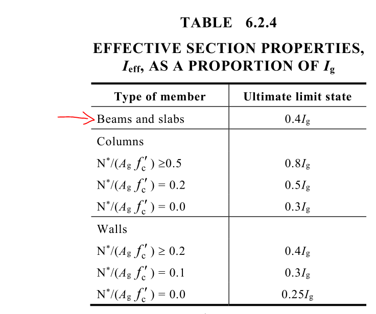
While many standards tell to consider the effects of cracking, creep and shrinkage (e.g. CSA A23.3-14 cl.9.5.1 and cl.13.6.2) even at Ultimate Limit State , many designers simply run linear analysis using stiffness based on gross area to design concrete slabs.

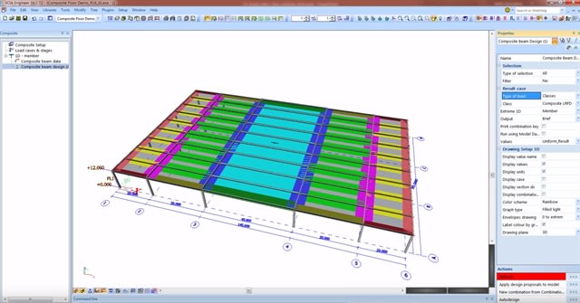
I did some tests on CSI SAFE and found that the difference in terms of moments were small between a linear model and "cracked" model. My "cracked" model used linear loads case based on stiffness at the end of a non-linear case. This non-linear case used loads from Dead + Superdead + 0.25*Live. I did not consider creep and shrinkage. The modulus of rupture fr was 0.6*sqrt(f'c).

So do you consider cracking in slab design at Ultimate Limit State on finite element model ?
If yes, how ?

Thanks for yours comments


Replies continue below

Recommended for you

You need to consider what the purpose of the analysis is. Non linear analysis generally means that extra moments, shears due to deflection are incorporated rather than having to use magnification factors or similar base on axial load.

For slab axial loads are generally low so the difference between the analysis at ultimate limit state will be low assuming similar cracked stiffness solutions are used. However newer programs like the nonlinear for sale deflections were stiffness changes greatly affect the outcome.

Overall because nonlinear, stiffness are calculated at SLS most will carry the same to ult.
 
The linear elastic solution gives the upper bound for the design of plates or any other reinforced concrete member and is thus a safe option. As far as I know, there exist no reasonably accurate methods for estimating the bending stiffness of istotropic (classic thin plate of constant thickness) or orthotropic (e.g., plate model that includes reinforcement inertia) reinforced concrete plates. Therefore, it should not come as a surprise that concrete plates are modeled by linear elastic methods in ULS.


In fact, determining the bending stiffness of simple concrete beams has also proven to be quite difficult - the reduced inertia properties (due to cracking) and reduction of young´s modulus (creep) are almost always overestimated or underestimated. Reinforced concrete design is not an exact science.
 
A bit late to the party, but the Australian standard (AS3600) recommends reducing the effective bending stiffness by the following amounts:
Capture_nh0nhq.png


I'd be wary about using results from ULS analyses that have used uncracked section properties since they may over/underestimate forces/stresses, especially at or around transfer beams.

That being said, I can't really see any benefit from using creep and shrinkage effects on ULS. Unless we're talking bridge girders, the effect of force redistribution due to creep/shrinkage should be minimal.
 
Thanks for yours comments.

Using these reduction factors from AS3600 (who are by the way similar to those in ACI-318-19 cl. 6.6.3.1.1) affects the moments around transfert beams and edge column, way more than with my non-linear analysis.

The relative stiffness between elements seems the most important.

Maybe that calculating the inertia with the equations given in cl. 6.6.3.1.1 gives closer results to my non-linear analysis.

Anyway, I would wish that Canadian code would be more explicit on this aspect.
 
Globally reducing the entire slabs moment of inertia will ultimately reduce the overall column/slab joint stiffness which for all but the first interior span will mean larger positive(span) moments and reduced negative(support) moments. The Exterior column will tend to see a larger unbalanced moment. With unreduced properties the negative(support) moments will tend to be larger as well as the unbalanced moment transferred to the support.

A true non-linear analysis will lie somewhere between these extremes as portions of the slab shell and column crack.

My Personal Open Source Structural Applications:

Open Source Structural GitHub Group:
 
Status
Not open for further replies.

Part and Inventory Search

Sponsor