Continue to Site

Eng-Tips is the largest engineering community on the Internet

Intelligent Work Forums for Engineering Professionals

  • Congratulations KootK on being selected by the Eng-Tips community for having the most helpful posts in the forums last week. Way to Go!

Concrete Support Structure over Old Pipe

Status
Not open for further replies.

bpstruct

Structural
Apr 23, 2008
136
Working on a project involving some new rail lines. There is an existing old wastewater line (60" diameter) about 15 feet below grade. The pipe is in questionable condition. The city (owner of the WW line) wants to avoid having any new loads translate down onto the pipe. I intend to design a short isolation structure over the top of the pipe. The structure will have a span of about 10-12 feet and will be supported by drilled piers. The structure will be cast on void forms. However, my concern is what happens when the train axles leave the structure. The loads will translate through the soil at a 45 degree (or some other debatable angle) and still impose load onto the top of the pipe. I originally thought of using sheet piling behind the drilled piers on each side to cut off the load, but I'm wondering how close to the back of the piers I can get with the sheet piling. Perhaps a better idea would be to use several closely spaced piers. If so, I wonder if they need to touch, or if I can leave a one-foot (or preferably bigger) gap between them.

We cannot excavate down to case the pipe because there are existing rail lines right next to these proposed rails. The existing WW line was cased beneath the existing rail lines, but it didn't extend out far enough to protect the pipe beneath the proposed rails. See the attached sketch.
 
 http://files.engineering.com/getfile.aspx?folder=565df181-b1eb-440d-b940-6b6654cc73ea&file=Rail_Structure_Sketch.pdf
Replies continue below

Recommended for you

If this us a streek pipe you could work out the stresses using API 1102.

It will give you some idea of forces without your structure.

Can you make the flat bit of the structure wider?

At that depth, the extra load on the pipe even from a railroad waggon is not that high so with your structure I certainly wouldn't be concerned about some load appearing at 45 degrees, and I'm a pipeline man.

Remember - More details = better answers
Also: If you get a response it's polite to respond to it.
 
It is actually a concrete pipe that was built in 1951. The depth does help, but even with the depth the pressure could be fairly significant. There will be no load transferred onto the uncased pipe from the existing rail lines, but there could be as many as 2-80 kip axles and 2-52 kip axles contributing load to the pipe. I think this would result in about 1200 psf additional load on the pipe. There is also going to be 4-6 feet of fill material added on top of the pipe.
 
Once you have the rig mobilised, it is not a big deal to install contiguous piling for the length required.
 
bpstruct - I would be reluctant to add a slab supported by drilled piers. Future differential settlement could make the railroad transition from the slab to soil a real problem.

Could you consider just a long (say 30') heavy structural slab-on-grade instead? With significant reinforcing steel, a thickness of 2' to 3' should do a good job of dissipating the load over a large area. Probably lower cost, too. There could still be some differential settlement issues, but not as dramatic.

[idea]
[r2d2]
 
I would look at installing a "High strength" CIPP liner through the existing pipe from one end of rail property to the other.
Then install your 'bridge' and sheet piles etc. If you could take the line out of service and jack a new casing to isolate it that would help. My guess a 60 inch pipe would require a large bypass and may not be able to be lined and or cut and replaced with the casing.

Richard A. Cornelius, P.E.
 
Back in the late 90's, we had to build a particular concrete piers to support an on-ramp for I95 SB in Bridgeport,Ct. The designer had a concrete cap over an existing storm drain some 6' below grade. The cap was supported by H piles on both sides. Your situation is somewhat similar with the exeception of the RR lines. Your concrete cap, supported by the drilled piers, will be loaded by the RR ties transmitting wheel loads. As far as outside the drilled piers, I would allow a couple of feet clearance, drive H piles on both sides of the pipe, then drive the interlocking sheets outside the H pile configuration, and preferably cross brace the H piles above and below the sewage pipes to resist lateral movement toward the sewage pipe. Also sacrificial zinc anodes would be a good idea if acidic soil exist. Ultimately if that segment of sewage pipe has to be replace, shoring is already in place.
 
Good comments. SlideRuleEra - Would an approach slab help transition on to the structure? Thinking of vehicular bridges - this is how that issue is handled. I don't want anything that is going to cause issues to be built, but we really aren't responsible for the rail performance anyway. We are just trying to protect the pipe. A different company is handling the rail design. There should be some means of handling that since there are rail bridges with presumably the same potential. I'm not sure the slab idea would work. The axles are spaced very closely together.
 
bpstruct - An approach slab would help, as a bridge contractor we built a few highway bridges designed that way. A long-term problem is the hinge where the approach slab joins the fixed structure.

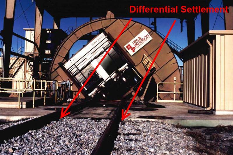
The differential settlement issue is real, we had to deal with it on an ongoing basis at the coal railcar unloaders at electric generating stations. Here is a typical photo, I marked where rail road bed maintenance has been performed for years:

Heyl___Patterson_Rotary_Railcar_Dumper-1_d6lde8.jpg


Suggest not ruling out a slab-on-grade without running the numbers. On a small scale (say the 30' length I mentioned) the axles are spread further apart than intuition suggests. While doing design work on one unloader I was surprised how well distributed the axle loads are. After thinking about it, they have to be. Any given railroad bed can support only so much.

[idea]
[r2d2]
 
I will keep thinking about the slab-on-grade idea. My understanding is the client wants no new load on the pipe, though. I just don't see how the slab-on-grade eliminates new load. I see how it spreads it out, but I don't think it eliminates it. The pipe was installed in 1951, and there is some question about its condition.
 
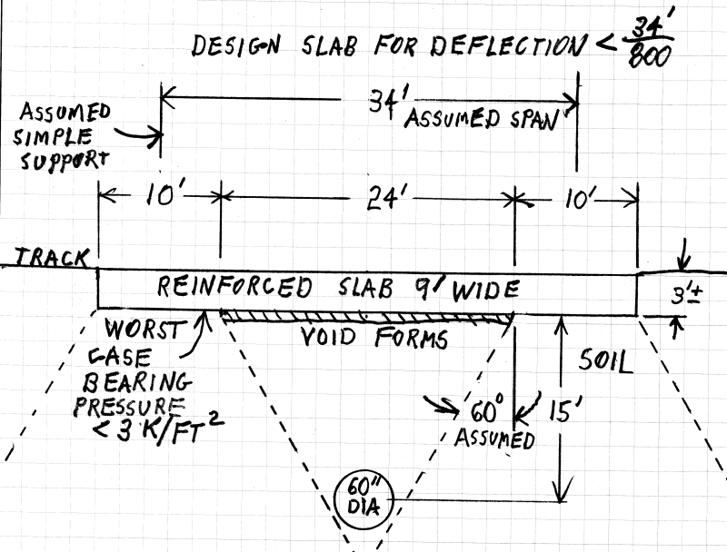
If the void forms shown on your sketch are used under the over-pipe portion of a (30' long x 9' wide x 3' thick) slab-on-grade, I bet the load on the pipe is lower than it would be in the deep foundation sketch (without approach slabs).

Assume the load is 80 kips per axle (Cooper E80), not 80 kips per wheel?

[idea]
[r2d2]
 
I will run a model the way you are suggesting too. I understand your suggestion to be to have a 30-foot long slab with void forms over the top just like I have them now. The difference being that the "foundation" for the structural slab is the portion of slab beyond the void forms on each side for your idea. For this idea, I think you would still need the sheet piling at each end of the void forms to prevent loads from translating at an angle through the soil and onto the top of the pipe.
 
That's good, either it works or it doesn't... worth checking I believe. If the requirement is for absolutely no applied load (zero) from the rail line, I agree the sheeting is likely required.

Keep in mind two things:

1. The 30' length is my first-order approximation, if a little extra length may be needed. If 35' feet is insufficient, extra length beyond that probably won't help.

2. The rail load on the adjacent track will apply some of its load to the uncased pipe length. Not much, but some. The load distribution footprint thru the soil takes place not only along the length of the track, but also perpendicular to the track.

Edit:
If you want to try avoid both loading the pipe and installing sheeting try modeling this. Be sure the axle spacing is realistic:

RR_Slab_k8gqxf.png


[idea]
[r2d2]
 
You should check geotechnical report for potential consolidation of compressible soils beneath the site. I worked on a project with a 54-inch concrete cylinder pipe in a steel casing that deflected about 9-inches under a 14-ft road embankment.
We are also evaluating a 12-inch sewer in a steel casing that crosses under a RR. The sewer appears to have settled about 6-inches since it was originally installed the early 1980's.
 
Status
Not open for further replies.

Part and Inventory Search

Sponsor