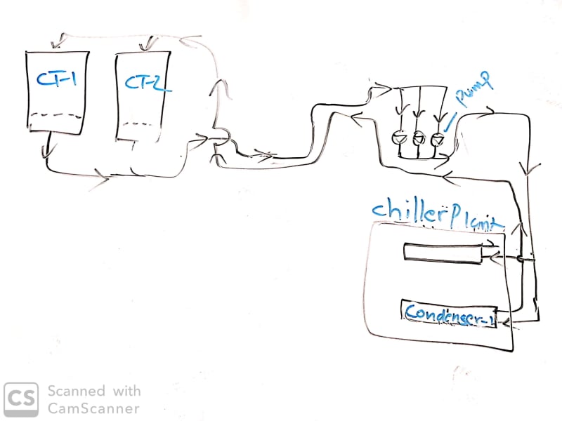
I have an existing centrifugal chilled water system for two blocks for residential complex where two chillers of 600ton*2(one duty one standby) with two cooling towers placed for block A and 530 ton*2 for block B. the system has passed 12 years. there is a common issue for both block. the position difference between chiller’s condenser and cooling tower around 80 meters. It means the only length of suction pipe between cooling tower and suction nozzle of condenser pump is 80 meter(260ft). The condenser pump(end suction) placed near the chiller, now operation had been facing from the commissioning time the following issues
1. The air is trapping on suction pipe, when open gauge port air is strongly drawing into the pipe, but it is working inefficient way from long time.
2. Both condenser pumps in the block A and the block B are, rated with 55 KW (35-meter head), in continuous operation throughout year even though at low ambient of winter season. After switching off the condenser pump, air immediately trapping to the suction line and overflowing the CT sump, and very hard to release the air from system and approximately takes six hours to back the system into the operation. so, the operators will not switch off the system until any breakdown happened. Clear-cut energy waste through this eccentric situation.
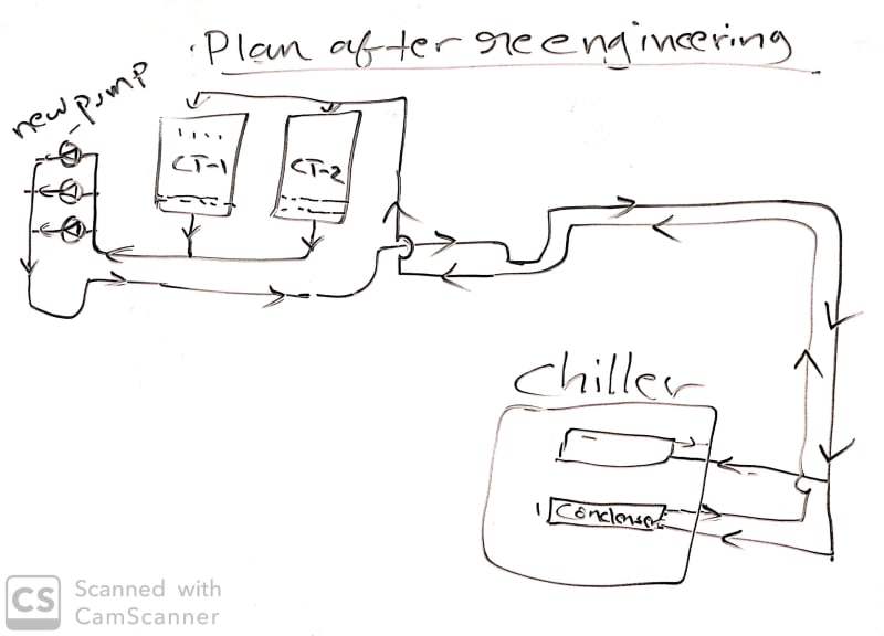
In the lights of these experience with this system, now I am thinking to do some retrofits with new thoughts and fresh head calculation. My plan is below,
Relocate the cooling tower to the above the roof of pump room, then could be reduce the pump head and save more energy, but it is more expensive, complicated and hard to take the structural assurance of the slab. Etc.
So, I planned to install more efficient new Grundfos pump (inline vertical) near the cooling tower. By which, I can reduce the suction pipe’s length as 15 meters. The NPSHA will be improved and 10 ft higher than the design pump. Primarily, I prepared an isometric drawing of condenser water circuit. re-calculated the pump head with same flow rate which comes with 37 kw with 22-meter head (70 ft). the existing pump head is 35 meters with 55 KW. This is the planning and progress so far. If any comment , suggestion or advice really would be appreciated.


