Eng-Tips is the largest engineering community on the Internet

Intelligent Work Forums for Engineering Professionals

  • Congratulations waross on being selected by the Tek-Tips community for having the most helpful posts in the forums last week. Way to Go!

Conflict on the correct way to show Pemnuts in a sheet metal drawing

Status
Not open for further replies.

jeff97070

Mechanical
Feb 14, 2013
52
0
0
US
Hello,


For years and many many products we would call out the Pemnut used in a sheet metal part as a flagged note like flag note 8 4X Pem M4X install farside. Then in the drawing view we would point to the hardware location with a flag.

A new person now say's industrial standard is to make an assemble of the sheet metal part and assembly the actual Pemnut model then add this assembly view in the fab drawing and then add a bill of materials, item one would be the part number of the sheet metal fab drawing and item 2 would be for the Pemnut.

Can someone tell me which one is preferred, again the way we have done this for 20 plus years has worked fine using flagged notes.

Thank you,

Jeff
 
Replies continue below

Recommended for you

It all depends on what you're doing with your drawing. The purpose of a drawing is to communicate the design designed by the designer reliably so it can be made by the person who makes it. If this drawing is going to your own shop floor, to be processed by some dude whose job it is to install PEMs all day and he has a fully stocked bin of all the sizes you need, I'd say no prob. If you're sending random drawings out of your department and they land who knows where at what new or current vendor, some new company that's not familiar with your drawings may or may not realize that providing the PEMs is part of their scope, or know how or where to buy them or install them correctly. You may get a delay when the guy on their shop floor goes, "Hey, where's the daggum PEMs I gotta stick in here?" because nobody ordered them because there was no BOM. If the extra work to make an assembly isn't worth the extra info conveyed, it's not worth the resources.

 
I have made them both ways: A part drawing with a note calling out PEMnuts and size/part numbers; or an assy with a BOM on the drawing calling them out. Either way the info is on the drawing with all pertinent info together.

Chris, CSWP
SolidWorks '17
ctophers home
SolidWorks Legion
 
"Industry standard" = "the way I did it at the last job"

The new way is probably more CAD friendly and maybe better for MRP system.
 
That's how I do it now. A sheet metal part and the Pem nuts into an assembly, then into a drawing with BOM. for us it allows purchasing and our fabricator to know the exact amount of Pemnuts to use and to bill for it per each assy drawing.

Scott Baugh, CSWP [pc2]
CAD Systems Manager
Evapar

"If it's not broke, Don't fix it!"
faq731-376
 
jeff97070,

Talk to your fabricator. If they don't know what you want, you won't get what you want.

I strongly prefer the assembly approach with the BOM on the fabrication drawing. Whoever is making your part needs to order the PEM nuts. A picture clearly shows which side of your part the nut is mounted to.

Left to my own devices, I prefer to attach an item balloon to the PEM nut. I have a note on the drawing stating "INSTALL THREAD INSERTS AS PER MANUFACTURER'S INSTRUCTIONS". The last place I was at dimensioned the hole, and added a note stating it was for a PEM nut.

When I model an assembly featuring your sheet metal part, I want to see the PEM nut. It occupies space I may want to use for something else. In the assembly model, I need to see that it is there, and on what side it is installed. I don't want to have to pull your drawing out.

--
JHG
 
Add the PEM nut into the sheetmetal part file, so you have a multibody part. I used to do this and create a weldment so I could get a BOM.
 
grunt58,

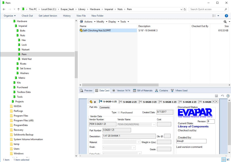
I cannot access SolidWorks at the moment. Can I pull the PEM nut out of a library, complete with meta-data, and insert it in the part model? This would be nice if the part is otherwise, a weldment.

--
JHG
 
Here is the PEM nut I use my SHeet metal parts. It exists in my own personal Toolbox folder. Unfortunately adding new fasteners with configurations to the Toolbox is next to impossible. So I have my own toolbox in the vault.

PemNut_in_Vault_qtt8xy.jpg


Hope this helps,

Scott Baugh, CSWP [pc2]
CAD Systems Manager
Evapar

"If it's not broke, Don't fix it!"
faq731-376
 
I insert it into an assembly. Sometimes I have just two parts in my assemblies. The Sheet metal part and the Pem nut. Sometimes I will use weld nuts instead and I put them in at the assembly level. If you use this in an assembly it has mate references built into it and it makes adding them very simple and it's far easier than inserting it in part.

Scott Baugh, CSWP [pc2]
CAD Systems Manager
Evapar

"If it's not broke, Don't fix it!"
faq731-376
 
We used a lot of pemnuts and pemstuds at a previous job. We created the sheet metal part, then created an assembly of the sheet metal part and pemnut. That way the BOM is associative and the shop knows what the assembly looks like.
 
Status
Not open for further replies.
Back
Top