rollingcloud
Aerospace
- Aug 9, 2022
- 174
[Reposting this thread as I had to remove my original post due to the inability to remove sensitive material.]
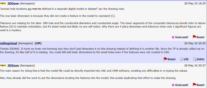
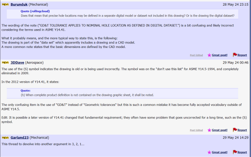
The size of the cutouts (bigger holes) is stated, but I have looked everywhere on the drawing and could not find the distance nor its tolerance. One of the drawing notes states, "GD&T TOLERANCE APPLIES TO NOMINAL HOLE LOCATION AS DEFINED IN DIGITAL DATASET." Does that mean that precise hole locations may be defined in a separate digital model or dataset not included in this drawing? Or is the drawing the digital dataset?
What is the function of the grid lines that do not seem to provide dimension nor location? Also, the true position of the fastener holes is strange. There is only one basic dimension, which is to the datum target C1. I still need to know the basic dimensions to datum A, B, and C in order to use that composite feature control frame.
Can I apply the .02 TP of the fastener holes to the bigger cutouts? Since they all share the same part, it would make sense for them to have the same positional tolerance.
The drawing does say that they have a photo contact master available for shop use, and undimensioned feature tolerance is +/- .03'', but PCM is more for inspection, right? For manufacturing purposes, we still need to know the distance between the holes and their exact locations.
See drawing here:


