Continue to Site

Eng-Tips is the largest engineering community on the Internet

Intelligent Work Forums for Engineering Professionals

  • Congratulations MintJulep on being selected by the Eng-Tips community for having the most helpful posts in the forums last week. Way to Go!

Connect 2 sketches for a solid

Status
Not open for further replies.

Bogdan1985

Mechanical
Jan 8, 2014
72
Hello everyone,
I have to redesign a frame. Everything works fine but the end of the frame rail. See the attached merged image. The original frame came from our partners from India and is full of mistakes. I created now 2 sketches with the beginning (larger) and the end of the "wedge" style frame end (smaller).
It does not work with sheet metal. Because for the radii. And it does not work with "draft".
Since hours I try to find a way to connect both sketches, to make a solid which I later like to "unite" with the main frame rail.

Do you know a way?

See attached.
Thanks Bogdan
 
 http://files.engineering.com/getfile.aspx?folder=fe8e43e9-7b73-460e-b4a6-668a1be23b5b&file=FRAME-END.jpg
Replies continue below

Recommended for you

Hi

I see the problem in any method you'll get wrong thickness.

What I suggests is to build a solid block with sharp edges.
and then round the two corners and finally hollow it
to the desired!thickness.
 
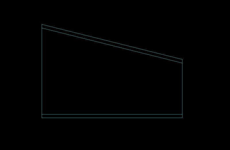
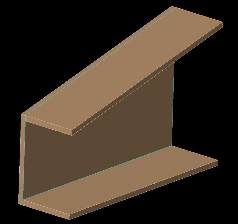
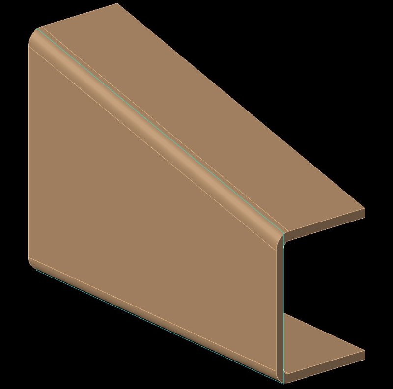
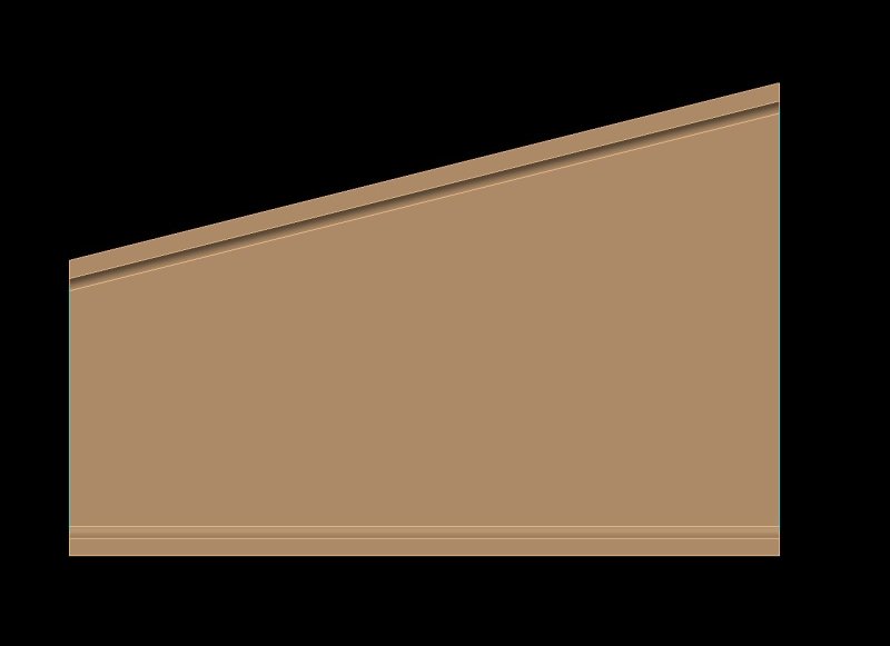
Other option is with one sketch illustrated as follows.

Draw a right angle trapezoidal shape and then add
Two lines to save as the thicknesses
One on on the right Angeles side and one on the other side
then extrud the trapezoidal shape to the thickness size
and then second extrude of the two thicknesses to the desired length.
 
TRAPEZ1_g4jxzo.jpg

TRAPEZ2_qa95ci.jpg
TRAPEZ3_mxbbb3.jpg

TRAPEZ4_dlcb10.jpg

 
What is the original problem ?
Creating this shape can be done in "millions" of ways, you mentioned one method yourself and a984928 proposed another.
( the big difference between the result there is the cross section of the upper bend, using arcs in the two sketches and a trough curves feature will produce a elliptical bend , which Sheet Metal cannot unfold. - since NX will approximate the full section the resulting face will be B-surface and not elliptical.)
but that should not be the problem. the Shape is for the eye almost identical.

Do you want to use Sheet metal to unfold ? Is this the problem ?
One way,in Sheet metal, could be using the Lofted Flange. - Then DO NOT try draw the bends, NX will create these for you.

Regards,
Tomas
 
 http://files.engineering.com/getfile.aspx?folder=346669cd-3a44-4fa7-b4de-cf1eacc65ac0&file=connect-two-sketches.prt
Thanks so fare. The problem is, I cannot touch the surfaces and even not the edges. This part is a botch
from India. I guess he started a mix of "jt-part" and solid with an unknown program. I ask him, but get no answer. Maybe is forbidden to answer. The "partners" over there are not very cooperative.

It doesn't work with sheet metal because it makes me ever again a step between the original rail and the wedge part. Although it is day off, I was in my company to test what your recommend to me. No success. I had a look in all tables about girders, nowhere is such a material thickness. And NX rejected the original radii numbers all the time.

All of the sudden I met an former coworker and he says, there is the possibility of a "bridge surface".
Has anyone an idea about that?

Thanks and have a healthy and successful 2018. I guess we will have a boom.
 
I'm confused. In your first post you say

I created now 2 sketches with the beginning (larger) and the end of the "wedge" style frame end (smaller)

And now you say

I cannot touch the surfaces and even not the edges.

And we haven't the real part.

I need help to help you

Thanks.
 
Hi a984928,

sorry for confusing you. The part is a mix of "jt" and Solid but you see in the tree "Body" only.
You can touch the faces, but you cannot isolate those faces or generating an edge for these faces.
The only edge you can copy in a sketch are the ends of the wedgy part. So I made 2 sketchs,
and with "Project Curves" I copied these curves into my sketch. I erased the most of them (because hundreds of curves and arcs)and made via end points and diameter analyses a new Sketch for each ends.

After I tried your way your described I get a step between the straight rail and the (larger) end of the
new wedge.

But I like a smooth "bridge" between the straight rail and the wedge part. My question now: Is there a way to combine both sketches to a solid, or before solid to a volume?

Thanks

 
To all my Helper,

thank you for the help. I completed it via points and surfaces and sent this to my manufacturing-engineer. He get almost a heart attack and says it is impossible to make in the back shop. He went to my group leader. The group leader called to India
and reordered the part again. This time in NX full model. Because the other end of the rail has a curved cut and cost a lot of to make.

This job was normally mine. But the companies sent all to India for a lower man hour costs. An I have to repair
this botch.

Thanks again!!

Bogdan
 
Status
Not open for further replies.

Part and Inventory Search

Sponsor