Navigation
Install the app
How to install the app on iOS
Follow along with the video below to see how to install our site as a web app on your home screen.
Note: This feature may not be available in some browsers.
More options
You are using an out of date browser. It may not display this or other websites correctly.
You should upgrade or use an alternative browser.
You should upgrade or use an alternative browser.
connect in parallel 02 transformer 8
- Thread starter zinki
- Start date
- Status
- Not open for further replies.
-
1
- #2
RRaghunath
Electrical
Yes, if the transformer vector groups are Dyn1 & Dyn11.
@ Mr. RRaghunath (Electrical)14 Jun 23 10:24
"....Yes, if the transformer vector groups are Dyn1 & Dyn11".
1. I am not sure they can operate correctly. There are five basic pre-conditions for two or more transformers to be connected in parallel, to operate correctly . One of the pre-conditions is the vector group (=phase displacement), a concern raised by Mr. zinki.
2. Transforms with Dyn1 & Dyn11 are 60 degrees apart.
3. Please advise/reconfirm that they can be connected in parallel and would operate correctly.
Che Kuan Yau (Singapore)
-
1
- #4
wcaseyharman
Electrical
I am assuming you’d have to reverse the phase rotation on one of those transformers to reverse the phase shift.
@ Mr. RRaghunath (Electrical)14 Jun 23 10:24
@ Mr. stevenal (Electrical)18 Jun 23 22:52
I am confused.
Please advise/reconfirm that Transforms with Dyn1 & Dyn11 with vectors 60 degrees apart are suitable for permanent connection in parallel and they would operate satisfactorily without undesirable circulating current.
Che Kuan Yau (Singapore)
@ Mr. stevenal (Electrical)18 Jun 23 22:52
I am confused.
Please advise/reconfirm that Transforms with Dyn1 & Dyn11 with vectors 60 degrees apart are suitable for permanent connection in parallel and they would operate satisfactorily without undesirable circulating current.
Che Kuan Yau (Singapore)
Hello Che, I had a look at the FAQ stevenal linked to, and the answer definitely seems to be YES, provided you connect as described . . . and as stevenal emphasized, perform phase checks across an open switch between the two secondaries to be parallelled before closing in.
CR
"As iron sharpens iron, so one person sharpens another." [Proverbs 27:17, NIV]
CR
"As iron sharpens iron, so one person sharpens another." [Proverbs 27:17, NIV]
che12345 said:Please advise/reconfirm that Transforms with Dyn1 & Dyn11 with vectors 60 degrees apart are suitable for permanent connection in parallel and they would operate satisfactorily without undesirable circulating current.
No, I cannot confirm such. The method I outlined connects them in phase.
The last link in the FAQ used to work, illustrating the phasor method proposed. I'll try another upload when I have a bit of time.
@ Mr. crshears (Electrical)19 Jun 23 09:33
"....#1. Hello Che, I had a look at the FAQ stevenal linked to, and the answer definitely seems to be YES, provided you connect as described . . . and ...#2. as stevenal emphasized, perform phase checks across an open switch between the two secondaries to be parallelled before closing in".
I have the following opinion for discussion:
1. The FAQ Mr. stevenal linked to is valuable, but is irrelevant to the topic. The illustrations summarized to a) observe the phasal displacement, b) observe the CT polarity c) the basic principle is instantaneous sum of i1 + i2 shall be zero for proper operation of a basic differential protective relay.
1.1. For Transforms with Dyn1 & Dyn11 with vectors 60 degrees apart, above condition can NOT be achieved.
2. For Transforms with Dyn1 & Dyn11 with vectors 60 degrees apart, perform phase checks across an open switch between the two secondaries would NOT be ZERO. Therefore, forced closing would result to undesirable heavy circulating current.
Che Kuan Yau (Singapore)
davidbeach
Electrical
The nameplates will say one thing and the connections will do something else. Any Dyn transformer can be paralleled with any other Dyn through judicious selection of which phase connects to which bushing. Nameplate vector group isn’t destiny, it’s just a point of departure.
I’ll see your silver lining and raise you two black clouds. - Protection Operations
I’ll see your silver lining and raise you two black clouds. - Protection Operations
Will you please vet me on this David.
1. Superimpose the star portion of a Dyn1 sketch on top of the star portion of a Dyn11 sketch.
You should have a six armed star with the arms separated by 60 degrees.
2. Switch any two leads to the delta.
That should flip the vector sketch 180 degrees so the two sketches line up.
We have got rid of the 60 degrees, but our phase rotation is reversed.
3.Switch any two leads to the star.
That will correct the phase rotation, but the phases may not line up properly.
4. Roll either the delta leads or the star leads until the phases align properly.
5. The leads may now be paralleled.
--------------------
Ohm's law
Not just a good idea;
It's the LAW!
-
1
- #13
davidbeach
Electrical
That's it. Proved it "in real life" as they say, when I had the secondary of a standby transformer shifted 60 degrees to lag the unit aux by 30 degrees rather than leading it by 30 degrees. Motor transfer on loss of unit aux became a piece of cake where it had been a repeated failure.
Nameplate vector diagram is valid if you connect the first phase, call it A and a, to the H1 and X1 bushings, then connect the next, B & b to H2 and X2, C & c to H3 and X3. But nothing says it has to be that way.
To make things really fun, consider a transformer we used to have (inherited from a different utility in the area) where the delta windings were as they normally are, but the wye windings were connected such that the ends normally at the wye point was brought out to the bushings and the ends normally brought out to the bushings formed the wye point. Needed detailed instructions as to how to connect a mobile (almost always connected as Dyn1) so that it would parallel with the station transformer.
Two types of transformers - those that produce 0, 60, 120, 180, 240 300 degree phase shifts and those that produce 30, 90, 150, 210, 270, 330 degree phase shifts but there are a lot more nameplate configurations.
I’ll see your silver lining and raise you two black clouds. - Protection Operations
Until you find one that the nameplate is wrong. But that should not happen very often.
And it gets confusing with ACB rotation. Good thing I don't have to deal with that anymore.
In general watch the nameplate drawings. Take pictures and compare to see that they are the same.
And keep track of phasing.
And it gets confusing with ACB rotation. Good thing I don't have to deal with that anymore.
In general watch the nameplate drawings. Take pictures and compare to see that they are the same.
And keep track of phasing.
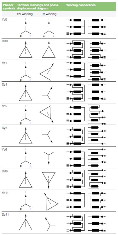
From Schneider.
D1 & D11 have different ways of connecting the delta. I don't think just swapping phases is going to cut it.
Muthu
D1 & D11 have different ways of connecting the delta. I don't think just swapping phases is going to cut it.
Muthu
-
1
- #18
NickParker
Electrical
please check the old threadLink
and also attachment from the forum member Sibeen
and also attachment from the forum member Sibeen
-
1
- #19
Take the diagram for Dy1 and renumber the top and bottom primary and secondary terminals. Make the top terminal III and the bottom terminal I. Now, primary Terminal III is connected to the right side of the Terminal II coil. Primary Terminal II is connected to the right side of the Terminal I coil. Primary Terminal I is connected to the right side of the Terminal III coil. Identical connections as Dy11.Edison123 said:D1 & D11 have different ways of connecting the delta. I don't think just swapping phases is going to cut it.
Hello Ladies and Gentlemen,
Let us get it straight. What Mr. zinki (Electrical)(OP)14 Jun 23 09:21 ask is/was " please is it possible to connect in parallel 02 transformer with different vector groups"
I am confused.
1. The answer I am expecting shall be a definite, either YES or NO stop. There is no room for MAYBE ???.
2. It is irrelevant to state that the windings can be configured to match ...... or the name-plate could be wrongly presented etc., etc.
3. Take note the key word is with different vector groups.
Che Kuan Yau (Singapore)
- Status
- Not open for further replies.
Similar threads
- Locked
- Question
- Replies
- 17
- Views
- 39
- Replies
- 2
- Views
- 26
- Question
- Replies
- 6
- Views
- 20
- Locked
- Question
- Replies
- 12
- Views
- 13
- Locked
- Question
- Replies
- 16
- Views
- 32