Continue to Site

Eng-Tips is the largest engineering community on the Internet

Intelligent Work Forums for Engineering Professionals

  • Congratulations GregLocock on being selected by the Eng-Tips community for having the most helpful posts in the forums last week. Way to Go!

Connect P&IDs and Loop Diagrams?

Status
Not open for further replies.

TiCl4

Chemical
May 1, 2019
616
I work at a smallish plant (~120 people) that grew from a small Mom&Pop Inc to be eventually bought by a Fortune 1000 company a few years ago. I came to the plant in 2017 and found that things were much different than my prior experience in the Cl2-based TiO2 industry. P&IDs were, when I arrived at Mom&Pop Inc a few years ago, under control of an outside electrical/controls engineering firm (essentially one guy) and had not been updated in ~20 years. There were no piping specifications, no maintenance software, etc. You get the idea.

Anywho, the current P&IDs show the typical sensing element->transmitter->controller->final control element loop all on the P&ID. If the sensing element and FCE are on separate P&IDs (which is common), the signal is sent to the other P&ID like normal process flows are.

In my prior life, the signals from the transmitters on the P&ID were all sent to the top of the drawing and directed you to the loop diagrams, which would, if followed, lead you eventually to the FCE on another P&ID. All of this inter-connectivity was vital for several functions - PFD calcs for LOPAs, function check procedures for safety interlocks, etc. This also had the advantage of de-cluttering the P&ID.

The P&IDs and the loop diagrams at my current place are entirely disconnected, currently. I am wanting to move to having the same system as my prior job, especially since the facility falls under PSM. The controls guy doesn't see the value in it.

What is your experience with this? What would you recommend as the course of action?
 
Replies continue below

Recommended for you

IMO, it is a business decision based on the requirements and needs among the Code & Regulation compliance, business management, O&M, and Engineering as well as the timing and cost.
One option is to propose to develop the P&IDs for an unit per your plan, and then, present the result to the Company Management, O&M, and Engineering for evaluations. It can be a sales process back and forth before the decision of rejection or acceptance.
 
Almost all drawings I have seen in the oil/gas business follow the control loop presentation style described in your present company. It is only in the tank farm design business that I've seen the style described in your previous company. Am more familiar with the style in your current company.
 
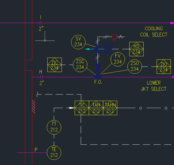
Perhaps a visual. The current company is mostly batch/semi-batch operation. P&IDs get very crowded. Too crowded, in my opinion. Below is a sample of our P&ID, with just a temperature probe and automatic valve w/ limit switches. A single reactor may have ~25 signals being sent off-page and ~15 process flows. Take a look below between the two different approaches. Any thoughts on the pros/cons of each?

Current: Signals to the PLC are terminated on-page, crowding up drawing space with the callouts. Also has the solenoid valve for the valve actuator in too much detail (does it really need its own name and an indication that it has a hand-switch bypass?).
image_rrwuj3.png


Alternate - all signals to the PLC are sent to the top of the page. The solenoid valve (or I/P for control valves) has been condensed.
image_batyww.png
 
I've never seen the second diagram below, but then I tend to deal with relatively simple stuff.

To avoid clutter, standard valves are usually detailed in a single sheet and then called out as type 1,2,3 etc.

All you are left with is ~FV 234 and type x
If the control element is local to the valve on the P&ID then link it, if not send it off the page with the reference signal.

For instruments the controller is OK, but I usually just see H and HH listed next to the transmitter element, not separate boxes.

Loop diagrams just go as pages for each control input or control item.

Trying to modify an existing set will be very difficult so I think you just need to update the existing and maybe tidy up the standard blocks to make it easier to read.

Just get it listed on the key sheets.


Remember - More details = better answers
Also: If you get a response it's polite to respond to it.
 
Cluttered as it may be, the first diagram is what I am used to - it gives the process engineer, and more importantly, the plant operator, almost all the critical info he / she needs to know on a single set of diagrams.
 
As an old fashion person, IMO, the first diagram is the better way with a complete info on one sheet. It won't be crowded on one sheet as it contains one equipment with the lines and controls associated with it. However, it's to be crowded if too many equipment or system showed on one P&ID with multiple control systems. also, it could be shown for the existing plants which been upgraded with new stuffs through years.
The typical solution is to split it into two or more drawings to improve the legibility but keeping all the controls on the same sheet. As mentioned, it can be easier references for all, including Disciplines, O&M as well as the Mgmt.
 
Status
Not open for further replies.

Part and Inventory Search

Sponsor