Navigation
Install the app
How to install the app on iOS
Follow along with the video below to see how to install our site as a web app on your home screen.
Note: This feature may not be available in some browsers.
More options
Style variation
-
Congratulations cowski on being selected by the Eng-Tips community for having the most helpful posts in the forums last week. Way to Go!
You are using an out of date browser. It may not display this or other websites correctly.
You should upgrade or use an alternative browser.
You should upgrade or use an alternative browser.
Connect Plate to HSS Tube 1
- Thread starter dik
- Start date
- Status
- Not open for further replies.
You could try a through plate in one direction and then have welded plates in the orthogonal direction.
Check the HSS limit states using DG24 or Packer & Henderson.
Perhaps a bracket type connection. I believe CastConnex (sp?) offers this type of solution.
There are also Hollo-bolts to check out, although I'm not a huge believer. Welding the plates is tricky, but not impossible.
Check the HSS limit states using DG24 or Packer & Henderson.
Perhaps a bracket type connection. I believe CastConnex (sp?) offers this type of solution.
There are also Hollo-bolts to check out, although I'm not a huge believer. Welding the plates is tricky, but not impossible.
- Thread starter
- #3
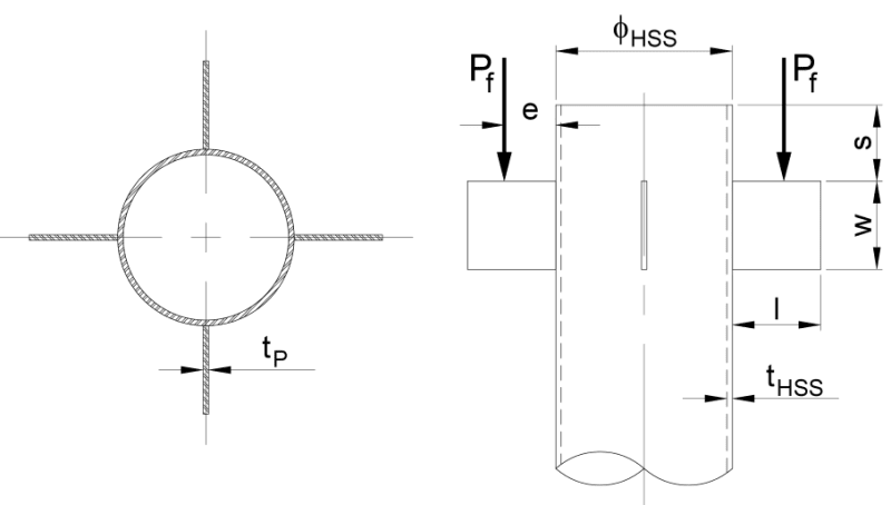
I've been presented with this as the problem and have to verify that it can be done. I haven't found anything that looks like the type of connection. The AISC design guide example, is similar, but uses tables in the AISC manual... I'm looking for a solution that I can calculate. I could't find anything in Packer's text. He has axial loads, but not moments. I would have thought this was common... maybe not.
Dik
Dik
For fin stability, I might try strut and tie and check the diagonal as a column. For the tube walls, I second the AISC design guide. I believe Packer was involved in that too and it's about as straight forward as it's likely to get. Tell us what table you need and we'll post it here.
To what extent will the load source stabilize or destabilize the fins laterally?
To what extent will the load source stabilize or destabilize the fins laterally?
Lomarandil
Structural
Could you even work in some sort of notched/cut out through plate in both directions (excuse the ASCII art below)? I suppose that depends on what diameter of HSS you have to work with, or you'd end up over-cutting the pipe slots to get the plate notches around each other
----
just call me Lo.
Code:
|------------------|
|    __________    |
|___/          \___|
----
just call me Lo.
DrZoidberWoop
Structural
AISC SCM 15th, Pg. 10-153: "As long as the HSS wall is not classified as a slender element, the local distortion caused by the single-plate connection will be insignificant in reducing the column strength of the HSS..... Single plate connections may be used with round HSS as long as they are non-slender under axial load (D/t<=0.11E/Fy). Yielding (plastification) off the HSS face has not been a governing limit state in physical tests. Punhcing shear/shear rupture should be checked as follows (Eq. 10-7a)."
Hope that helps. I'd check the above, the eccentric weld group, and then plate checks.
Hope that helps. I'd check the above, the eccentric weld group, and then plate checks.
- Thread starter
- #8
- Thread starter
- #11
- Thread starter
- #12
retired13: "Also, I think a FEM verification will be very helpful for this case." This would be OK if it were for several projects... not a single 'knock off'.
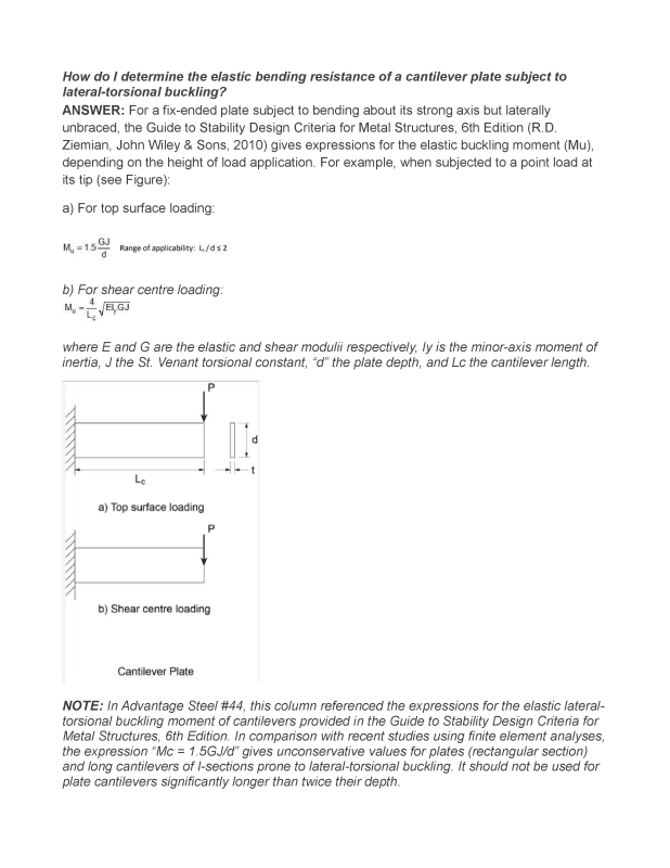
Do you know of a formula (couldn't find it in Rourks) for a cantilevered plate, loaded at the top in the stiff direction fixed at the side and at the top against rotation and translation. The top of the plate has an HP section welded to it, providing the load. It's so much stiffer than the 'fin plate' that it could easily be treated as a fixed condition.
Dik
dik,
I think moment capacity check was preclude for round HSS with simple shear tab connection. I suggest the following steps to design the connection:
1. Trail select a plate size thru buckling criteria.
2. Calculate weld demand, and select weld size, thru conventional method (I don't think you need assistance from AISC table).
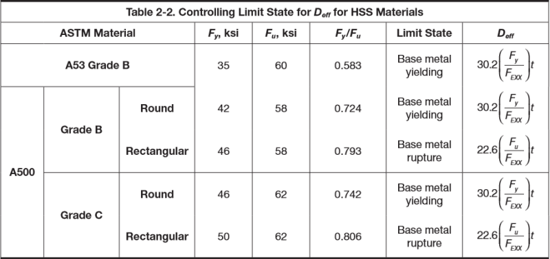
3. Go to paper table 2-3 (p.9) to get minimum plate thickness (tmin) per weld size selected.
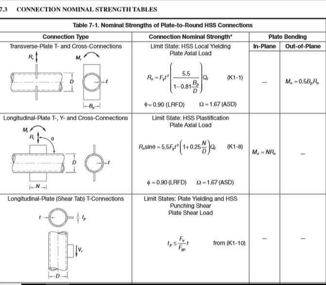
4. Go to paper table 7-1 (p.79) to fine tune plate thickness and HSS wall thickness. (Please read CH7 opening statements)
This is not a straight forward method, but should work out fine, unless you have other complications.
- Thread starter
- #14
-
1
- #15
dik,
I believe you have already noticed that the guide actually ignores effects from both flexural and punching shear on the HSS, as long as the HSS wall is thinner than the shear tab, which should yield first (Fu/Fyp is a constant always > 1). This may simplify your programming quite a bit.
I believe you have already noticed that the guide actually ignores effects from both flexural and punching shear on the HSS, as long as the HSS wall is thinner than the shear tab, which should yield first (Fu/Fyp is a constant always > 1). This may simplify your programming quite a bit.
- Thread starter
- #18
dik,
Found the background material of ignore punching shear from CIDECT Design Guide 9. Link to the source,
Found the background material of ignore punching shear from CIDECT Design Guide 9. Link to the source,
Over a wide range of connections tested by Sherman (1995, 1996), only one limit state was identified for the RHS column. This was a punching shear failure related to end rotation of the beam when a thick shear plate was joined to a relatively thin-walled RHS. Two connections failed when the shear plate pulled out from the RHS wall at the top of the plate around the perimeter of the welds. A simple criterion to avoid this failure mode is to ensure that the tension resistance of the plate under axial load (per unit plate length) is less than the shear resistance of the RHS wall along two planes (per unit plate length). Thus (Sherman 1995, AISC 1997), ø1 f,p,y tp · (unit length) < 2 ø2 (0.60fc,u) tc · (unit length)
In the above inequality the left hand side, the tensile strength of the plate, is multiplied (for limit states design) by a resistance factor of ø1 = 0.9 for yielding. The right hand side of the inequality, the shear strength of the RHS wall, (for which the ultimate shear stress is taken to be 0.6 of the ultimate tensile stress), is multiplied by a resistance factor of ø2 = 0.75 for punching shear failure (AISC 1997).
Hence tp < (fc,u/fp,y) tc
- Status
- Not open for further replies.
Similar threads
- Replies
- 3
- Views
- 4K
- Locked
- Question
- Replies
- 8
- Views
- 5K
- Question
- Replies
- 16
- Views
- 2K
- Replies
- 17
- Views
- 4K
- Question
- Replies
- 9
- Views
- 6K


