Continue to Site

Eng-Tips is the largest engineering community on the Internet

Intelligent Work Forums for Engineering Professionals

  • Congratulations KootK on being selected by the Eng-Tips community for having the most helpful posts in the forums last week. Way to Go!

Connecting a rafter to a shell 1

Status
Not open for further replies.

T2ioTD

Civil/Environmental
Feb 4, 2020
38
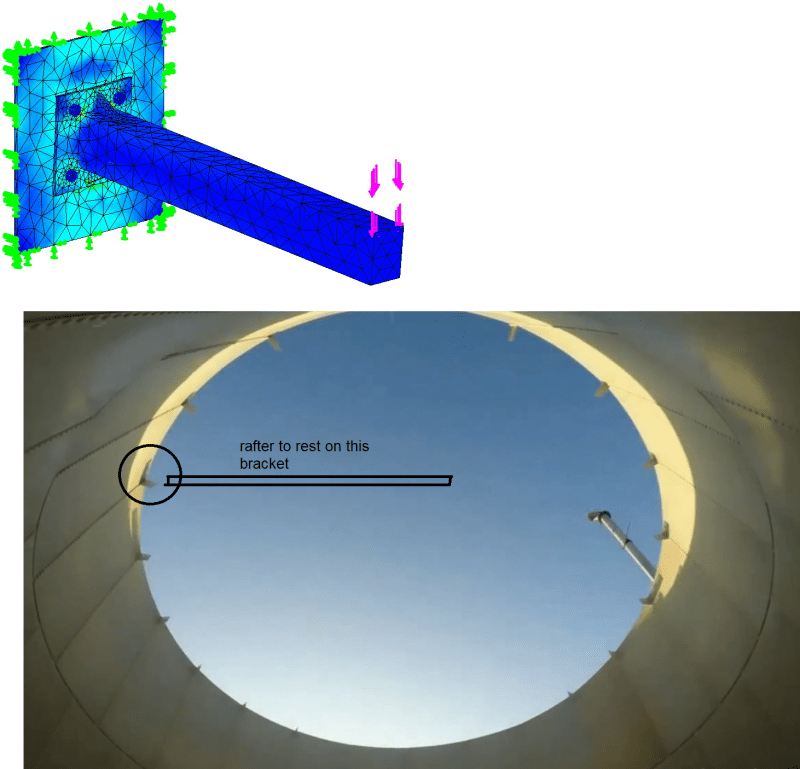
I couldn't find any reference but a tiny one (I will mention it at the end of this text) about how to derive the stress (even an approximation of it) of a shell under a point load acting along its surface. For instance: checking whether the loads exerted by a rafter attached to a shell is acceptable or no. The only thing close I could find is the design of anchor bolt chairs connected to a tank in AISI T192, but this is a special case I suppose and is not useful for the general case.
Any help is greatly appreciated. I will end up doing a SAP model, but I hate to take this route and not have even something rough done on Excel.
While the image below show moments being transferred, that is not important for me. At least I could have a pinned connection with only an axial load.

Regards
tmp_api_jp4z9d.png
 
Replies continue below

Recommended for you

Isnt there a continuous stiffener (top angle) on the other side of shell...on the same elevation as rafters?
 

Klitor:
I'm new to tank design. In API650 which deals with welded tanks, there is. But in API 12B which deals with bolted tanks, I simply don't know exactly. It's not clear in the code (maybe there the shells forming the top ring are flanged and that make them stiffeners, but I'm not really sure).
 
I can't see how those are connected in the photo. Presumably, that clip is at or very near the top of the shell, unlike your FEM detail.
It's possible they treat the clip-to-rafter connection as a moment connection (although with very low moment) and then the connection to the shell is just a shear connection.
Bednar's pressure vessel handbook gives an approximation for line loads on a shell, but it will usually give very low allowable loads.
WRC 107, 297, etc. methods include square moment loads on a shell. But a thin shell like that may be outside of the thickness ranges considered.
For a bolted tank manufacturer using certain fixed radii and thickness combinations, it would be feasible to do full-size testing on such a connection; whether or not they actually have, I don't know.
 
Status
Not open for further replies.

Part and Inventory Search

Sponsor