Eng-Tips is the largest engineering community on the Internet

Intelligent Work Forums for Engineering Professionals

  • Congratulations waross on being selected by the Tek-Tips community for having the most helpful posts in the forums last week. Way to Go!

Connecting a substation double 138 kV busbar with a disconnector 2

Status
Not open for further replies.

Bronzeado

Electrical
Jan 6, 2008
267
0
0
BR
Hi folks,

Please, find attached a double busbar configuration where the circuit-breaker that connects the busbars does not exist and the busbars connection is make by a normal disconnector, which is wearing out quickly.
The questions are:
1. Why this happens (disconnector wearing out so quickly)?
2. Is this normal disconnector applied wrongly?
3. What kind of disconnector shoud be applied in this case (specification)?
4. What kind of phenomena occur during disconnector operation?

Cheers,

Herivelto S. Bronzeado
Brasília, Brazil
 
Replies continue below

Recommended for you

Wait, you're saying you do not have a bus coupler breaker? When electrically splitting the bars (opening the coupler), the opening should only be done with a breaker. The voltage difference and phase angle (current) is simply to great between busbar 1 and busbar 2 for an ordinary disconnect to break satisfactorily.


Side note: When doing switching on bays the coupler should always be closed and all disconnects compliant with IEC-62271-102 Annex B.
 
If there is no breaker in the bus coupler, it is as good as a single busbar arrangement. Disconnector in Bus coupler circuit should never be operated unless one of the busbars is dead completely.
There are fast acting disconnectors available in the market that can be operated on load and expected to break load currents without excessive wear of contacts. IEC 62271-102 for HV disconnectors doesn't list current interruption capability for disconnectors (except saying negligible current). So, you have to find out from manufacturers.
Standard solution I suppose is installing a circuit breaker in bus coupler circuit.
I guess what you have currently is an off load disconnector which is the standard generally (with buscoupler breaker available).
With the fast acting disconnector, you may be able to operate the disconnector with both busbars live. Still, in the absence of buscoupler breaker, both busbars have to be isolated in case of a fault in one of the busbars.
 
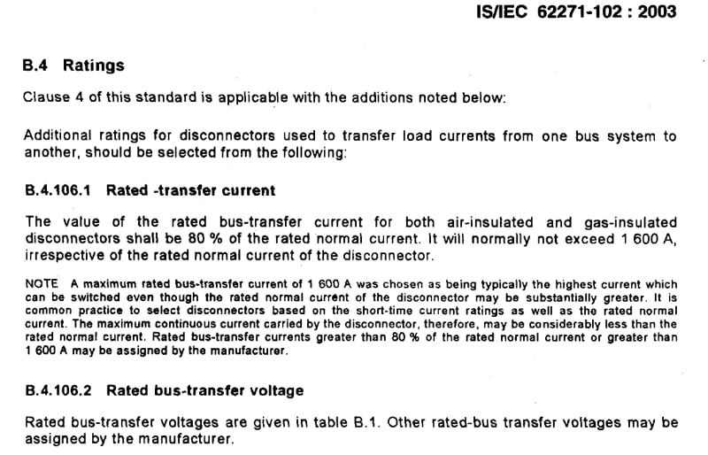
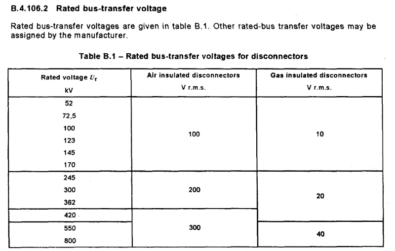
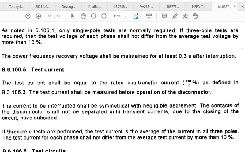
Not true, IEC 62271-102 Annex B does list the current at 80% of rated normal current with a voltage of 100, 200 or 300 volts:


Clipboard01_uy4mnw.jpg


Clipboard03_kpf1in.jpg


Clipboard02_ojn6p5.jpg


Forgive, but I keep seeing this pattern (not here, the internet in general) where I (and others) will post something factual only to have it falsely discredited by someone who hasn't read the actual law, data, article, ect in regards to the subject matter.

I'm not directing this at you RRagunath, just a pattern as of late.

Causally ask- where are you getting negligible current from?
 
Mbrooke, I am sorry if I offended you (that was not at all my intention). I have learnt quite a bit going through your posts all these years. Thanks.
With regard to the questions you had, hope below will help clarify.
Bus transfer is supposed to be without interruption. This is the definition from IEC
"3.7.122
bus-transfer current switching
opening and closing of disconnectors under load when this load is not interrupted, but
transferred from one bus to another"
With regard to the ability of disconnectors to make or break negligible current in general, see below from same IEC:
"8.102.5 Selection of a bus-transfer current switching capability for disconnectors
of 52 kV and above
Although disconnectors are, by definition, only capable of opening and closing a circuit when
either negligible current is broken or made or when no significant change in the voltage
across the terminals of each of the poles of the disconnector occurs.."
 
It is alright. Its not you. :) To be fair there is a LOT of confusion, controversy, and policy variants about just what any individual isolator can break.


When disconectors are opening with more than several hundred volts across their contacts without attachments the amount of current must be kept minuscule in comparison to their rated current carrying capacity. Typically no more than bus section or busbar charging current. Milliamps at most.

Attachments such as whips, horns, ect can increase the breaking current to allow for interrupting transformer magnetizing current, short lines, CVTs, ect. A few amps at most/best.

SF6 interrupter attachments can be added to break full load current at full voltage. 3000-4000 amps at most/best.

The above covers tens of thousands of volts across the contacts and/or interrupter attachments.

Now, in single breaker double busbar*, with the buscoupler closed, the voltage between bar A and bar B is typically around 100 volts.

Some isolators can break several thousand of amps at 100 volts when transferring between bars in closed transition.

I say some, because ironically attachments like whips, whiskers, ect designed to increase current dropping capacity at higher voltages can actually melt from the several thousand of amps of current.

And of course some switch designs will pit or wear out more breaking 1000 amps at 80 volts.

But generally speaking a standard disconnector without attachments can, without damage:

1) Interrupt full voltage at several hundred milliamps.

2) Interrupt full current at several hundred volts.

Key word is generally.

*Ring bus, breaker and a half, double bus double breaker, ect typically also see several hundred volts across any disconector if one ore more parellel galvanic paths exist between said disconnect.

> Just to be clear I am using the words "isolator" and "disconnector" interchangeably in this thread.

Any folks reading this feel free to correct me, I could be slightly off on a few numbers.
 
MBrooke and RRaghunath,

Thank you very much,for this interesting discussion on HV disconnectors.

Can I summarize that a standard disconnector can only be applied to open / close transfer bars with different loads if the voltage difference between the bars is in the range of a few hundred volts and the current in the disconnector is negligible?
In this case, the application of a standard disconnector to operate this double busbars is wrong, being necessary to modify this configuration
The quick wearing out in the disconnector contacts is due to the busbar operational condition, where the load difference in each busbar is causing an values in the disconnector currents and in the voltage differences between the bars may be aout of expected range.
Am I right?

Cheers,

Herivelto S. Bronzeado
Brasília, Brazil
 
The thing is bar 1 and bar 2 are essentially two different systems once the coupler opens. The voltage and current difference can be very large. You need a breaker, or in the least SF6 interrupters.
 
Thanks Mbrooke,

Now, considering that the busbars 1 and 2 have different loads but are fed by the same transformer.
In this case the bus-transfer voltage may be small and the bus-transfer current will depend on the load difference.
Do you think I can use a standard disconnector to close/open this transfer busbar system without wearing out its contacts?

Cheers,

Herivelto S. Bronzeado
Brasília, Brazil
 
Mbrooke,

I don't know exactly what is the substation configuration but I probably there are circuit-breakers between the transformer and the transfer busbars.

The only thing I know is that there are no circuit-breaker between the transfer busbars, with the interconnection being done directly with a standard disconnector, of which contacts are wearing out too quickly. The disconnector is operated frequently.

If you have any papers on this subject, I would appreciate if you can send them to me (bronzeado@ieee.org). Thank you in advanced!

Cheers,

Herivelto S. Bronzeado
Brasília, Brazil
 
I must be missing something...

When I look at the diagram posted, all loads appear to connected to a common secondary winding on the transformer; the only way there should be an issue [ and the only thing that makes sense to me ] is that there are two separate load windings without galvanic connection, as only that can cause switch damage; otherwise you're just opening a loop, in which case load currents will naturally re-distribute...

...at least the way I see it.

CR

"As iron sharpens iron, so one person sharpens another." [Proverbs 27:17, NIV]
 
"Do you think I can use a standard disconnector to close/open this transfer busbar system without wearing out its contacts?"
Disconnector for bus transfer refers to the two bus disconnectors in each feeder which are used for transferring the feeder from one bus to the other. I have seen standard disconnectors being used for this application.
In buscoupler circuit, I don't think a standard disconnector can be used unless you decide to operate it permanently closed (and operate only when one of the busbars is dead).
 
Thank you crshears and RRaghunath for your new imputs!

crshears, the "original" diagram is again attached.
I don't know exactly the substation configuration. So, we can see this as an hypothetical problem.
As you said, the only way that can cause switch damage is when it open/close circuit without galvanic connection. So, in this case, a standard disconnector can not be used. That is correct?

RRaghunath gives yours same advice and Mbrooke said to forget the disconnector and get a interrupter to operate that transfer busbars (give up).

So, in my view there are two conclusions:
a) the application of that disconnector is wrong; or
b) the disconnector is not of good quality.

Mbrooke, RRaghunath and crshears, are you with me?

Have a nice Sunday!!!!

Cheers,

Herivelto S. Bronzeado
Brasília, Brazil
 
Status
Not open for further replies.
Back
Top