Continue to Site

Eng-Tips is the largest engineering community on the Internet

Intelligent Work Forums for Engineering Professionals

  • Congratulations LittleInch on being selected by the Eng-Tips community for having the most helpful posts in the forums last week. Way to Go!

Connection repair/replacement in double tee system

Status
Not open for further replies.

GC_Hopi

Structural
Jun 24, 2018
551
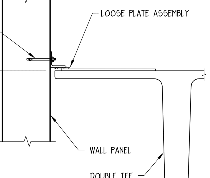
This project has precast panels and a double tee roof. There is a field fit up issue and the CIP embed plate is the double tee flange can not be used. The precaster has proposed a new connection by welding a few #4 bars on a plate and cast this into the topping for the double tee. This is fine and dandy but I have a bit of an issue with their proposal to NOT use any chairs to elevate the #4 to ensure good consolidation around the bar. It seems like the bar is a natural splitting plane. Precaster is claiming the double tee flange counts as concrete and the #4 is being developed. Is there any language in ACI stating that the concrete for bar development needs to be fresh concrete?

image_dkz0c5.png
 
Replies continue below

Recommended for you


As far as my knowledge , the splice length formulas are defined for the reinforcement in freshly placed concrete.
In your case, #4 rebar will lay on the exiting, hardened concrete . What is the reason for not using a spacer around 20 mm?
Another option , increase the splice length 20% assuming the bar is bundled.


This is typical repair method.
I guess Hopi is concerned about enough bonding because some portion of rebar will touch hardened concrete.
This is kind of gray area which needs engineering judgement.

The following technical note can help you.

Seismic Design of Precast Concrete
Diaphragms
A Guide for Practicing Engineers
 
JohnRwals said:
I guess Hopi is concerned about enough bonding because some portion of rebar will touch hardened concrete.

Yes, that is the concern and maybe you loose 50% of the bar surface area if the consolidation is bad. Also it is amplified by the fact that the connection is going to take the out of plane loading from the wall ie connection will mainly see tension. It does appear to be a gray area that I wish ACI or PCI would be more clear about that. The tech note you referenced only mentions needing to provide cover below the reinforcement at joints but all the figures show the reinforcement centered in the topping. So go figure.


image_smiuqd.png
 
Status
Not open for further replies.

Part and Inventory Search

Sponsor