Eng-Tips is the largest engineering community on the Internet

Intelligent Work Forums for Engineering Professionals

  • Congratulations waross on being selected by the Eng-Tips community for having the most helpful posts in the forums last week. Way to Go!

Constant torque in pendulum

Status
Not open for further replies.

Saleh abbasi

Mechanical
May 27, 2023
15
US
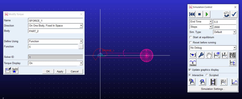
Hello everyone, I apologize for using this platform to ask my question. In Adams software, I am currently working on a simulation where I am applying a constant torque to a link that behaves like a pendulum. The system has no other forces acting on it, such as gravity or friction. According to the formula T=I*alpha, the relative angular acceleration should remain constant throughout the simulation. However, I have observed that in some instances, the acceleration becomes zero while in others it continues to increase.

I am seeking advice on how to obtain accurate and consistent results in my simulation. Any suggestions or recommendations would be greatly appreciated.
 
Replies continue below

Recommended for you

1_jngwdn.jpg


2_xauels.jpg


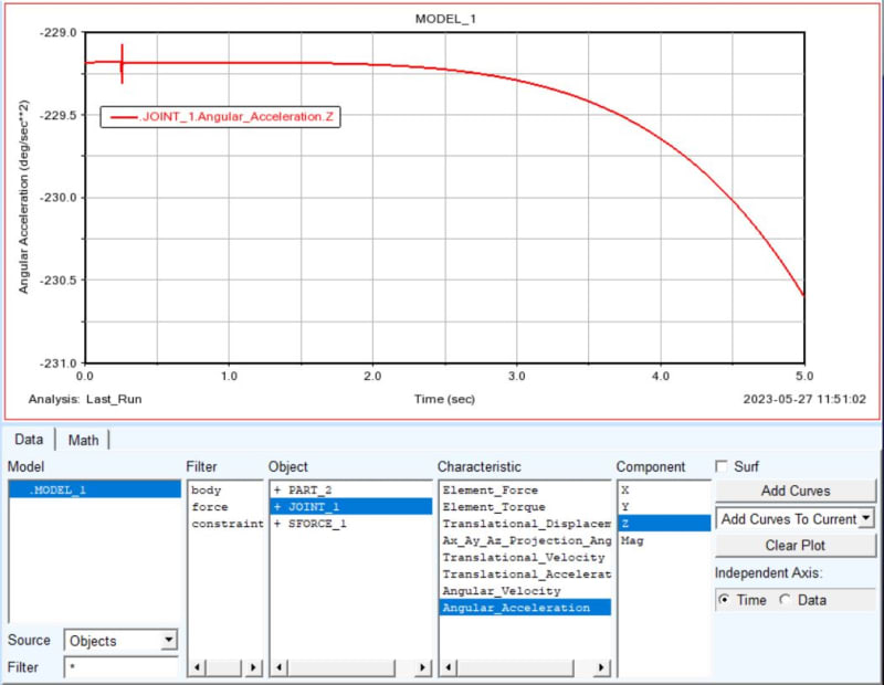
As you can see the Angular Acceleration changed. I try all measures (from torques, body and joint) all results is same, also i create an angle measure an derivates it, the result is same.
 
how does the inertia of the link affect the problem ?

"Hoffen wir mal, dass alles gut geht !"
General Paulus, Nov 1942, outside Stalingrad after the launch of Operation Uranus.
 
To simplify the model, I have inserted a point mass body in the end of the link, which has a spherical shape. This ensures that the moments of inertia along the x, y, and z axes (I_xx, I_yy, and I_zz) are zero. Even if these values were not zero, the same problem would still exist. The length of the body is 0.5 meters and it has a mass of 5 kilograms. Therefore, the inertia that affects the joint is given by the formula md^2 = 5*0.5^2 = 1.25. The torque is 5 units, which can be used to calculate the angular acceleration using the formula (alpha = T/I) 5/1.25 = 4 rad/s^2. In degrees, this is equivalent to 4*180/pi = 229.183 deg/s^2. Initially, these results provide the correct answer, but the angular acceleration changed!
 
"The torque is 5 units" ... you mean 5 Nm.

I think initially the torque accelerates the mass as calculated from rest. Once the acceleration is applied, I think the mass is no longer at rest, and so some of the applied energy have gone into accelerating the mass, and so the acceleration of the system decays.

But I could be wrong ...

Is weight (gravity) part of your model ?

Thinking about it, how does the mass react to a torque being applied ? I can see it moving because a force is applied, but a torque (a couple) ?

Is the link modelled as a rod ?? (or a beam)

"Hoffen wir mal, dass alles gut geht !"
General Paulus, Nov 1942, outside Stalingrad after the launch of Operation Uranus.
 
The gravity was not considered in the model, and no other forces were included aside from torque. Although the formula is correct (you can check it, or determine it with Lagrangian method), I need to validate the simulation for my main model - the RRR manipulator. However, since the results obtained from the simple pendulum are inconclusive, I cannot proceed with controlling the robot until I am able to validate the simulation using the RRR manipulator.
torque is 5 Nm and link is rigid, (if you asking for flexibility it's not.)
My apologies if my grammar has not been correct.
 
Does it look different if you double the number of steps (smaller Delta T)?
 
when you say you apply a torque ... what exactly do you mean ?

if you have a link constrained at one end, and apply a torque (or a couple) at the other end, the that torque will be reacted at the constrained end (and the link will carry that moment). no?

if you apply a 5N force (down) then the link will rotate about the constrained end.

"Hoffen wir mal, dass alles gut geht !"
General Paulus, Nov 1942, outside Stalingrad after the launch of Operation Uranus.
 
how do people figure this link will behave (with a torque load applied) ??

I know how it would react to a force input, but have trouble seeing the link reacting to a torque load. It is possible that at rest there is a locking pin somewhere in the system, so that the applied torque is reacted as a couple between the pivot point and the locking pin. Then when the locking pin is released (at time = 0), now there is a force imbalance on the link and I'd expect it would move in a direction opposing the locking pin reaction (as though the opposite force were applied to the link). Then I'd expect the link (or link and mass as the OP writes) would spin against the applied torque ... a dynamic balance to the applied torque. This feels like a continual acceleration ? Thoughts anyone ??

"Hoffen wir mal, dass alles gut geht !"
General Paulus, Nov 1942, outside Stalingrad after the launch of Operation Uranus.
 
I will try to speculate on a simpler example. Let's say there is no gravity or other forces. A conditional vacuum or outer space. If you hypothetically need to push an asteroid, then it is enough to apply force once, and then in accordance with Newton's second law:
"in inertial reference frames, the acceleration acquired by a material point is directly proportional to the force causing it, does not depend on its nature, coincides with it in direction and inversely proportional to the mass of the material point."
The same is true for angular force. I suppose the point is that the applied moment of FORCE acts every step of simulation, that is, it seems to increase the force/moment vector and, consequently, the acceleration given to the body. Try to apply the moment impulsively (for example, turn it on and off after a short period of time using the STEP function), and you will see that as soon as the moment disappears, it becomes zero, the increase in angular velocity will stop.
 
Thanks to Jennifer James for suggesting the change solver that helped me to solving problem with WSTIFF integrator. Does Adams have a solver like ode45 in MATLAB, which uses the Runge-Kutta method? Additionally, if we can't determine the formula of the model, how can we validate the results obtained using the Adams methods.
 
Whomever is posting as JenniferJames is very likely to be using ChatGPT to create answers.

Clever. The problem is that ChatGPT is meant to give convincing answers, not correct ones.

Look st the replies. In one day, 28 replies.
 
It appears to me what I would expect if the weight is not constrained to a fixed radius and the radius changes with angular velocity. It's poor practice to examine only one variable when a model is misbehaving. You should have plotted angle, angular velocity, applied torque, and radius to the mass to ensure that everything you thought was fixed remained fixed during the simulation.

 
"Thanks to Jennifer James for suggesting the change solver that helped me to solving problem with WSTIFF integrator. Does Adams have a solver like ode45 in MATLAB, which uses the Runge-Kutta method? Additionally, if we can't determine the formula of the model, how can we validate the results obtained using the Adams methods." ...

do you mean that a different integration method "solved" the problem ?

Your plot shows (as I see it) that some angular momentum is being "lost" (or not accounted for in the plot). Did you figure this out ?

Have you figured out the dynamics of the problem ? How does the link respond to a torque load ? Physically, what does this mean ??

"if we can't determine the formula of the model" ... I find this statement troubling ... you've changed the integration method applied. Your code (Adams ?) should explain the difference between the two, and when it is appropriate to use which method.


"Hoffen wir mal, dass alles gut geht !"
General Paulus, Nov 1942, outside Stalingrad after the launch of Operation Uranus.
 
Status
Not open for further replies.

Part and Inventory Search

Sponsor

Back
Top