vandongenp
Industrial
Hello,
I'm trying to perform a simulation whereby i transport a paper sheet between two pair of pressure rollers.
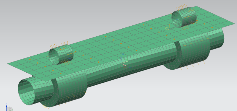
- The lower rollers are fixed in the translation directions.
- The upper rollers are performing a transient movement towards the lower rollers,
so there will be a contact force between the sheet and the roller pairs.
When the pressure rollers are finished with the downwards movement i perform a transient rotation of the lower rollers of 45 degrees.
I use solution 601 129, the simulation is working oké, but i get some slip between the two contact surfaces.
I expect a paper transport approximately of 13.75 (diameter roller 35mm with a rotation of 45 degrees)
The result that i get is around 8 mm.
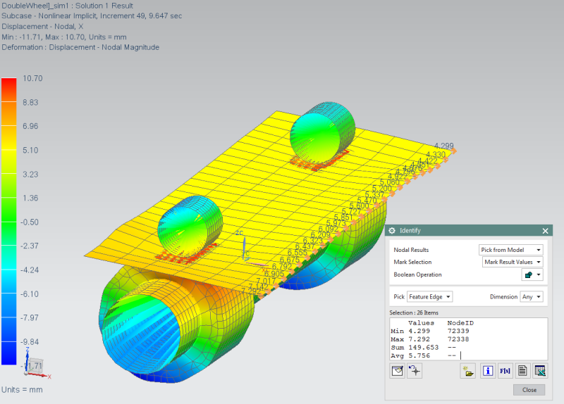
I try to adjust a lot of parameters like contact/ time step size / damping /etc, they all have influence on the end result, but i cannot manage to get a realistic result.
I added the FEM and SIM file.
Hopefully somebody can help me to understand this problem.
The simulation and fem file
Kind regards Peter
I'm trying to perform a simulation whereby i transport a paper sheet between two pair of pressure rollers.
- The lower rollers are fixed in the translation directions.
- The upper rollers are performing a transient movement towards the lower rollers,
so there will be a contact force between the sheet and the roller pairs.
When the pressure rollers are finished with the downwards movement i perform a transient rotation of the lower rollers of 45 degrees.
I use solution 601 129, the simulation is working oké, but i get some slip between the two contact surfaces.
I expect a paper transport approximately of 13.75 (diameter roller 35mm with a rotation of 45 degrees)
The result that i get is around 8 mm.
I try to adjust a lot of parameters like contact/ time step size / damping /etc, they all have influence on the end result, but i cannot manage to get a realistic result.
I added the FEM and SIM file.
Hopefully somebody can help me to understand this problem.
The simulation and fem file
Kind regards Peter