Hello everybody,
I come to your help because I have tried everything and I cannot make a simple contact work on Nastran.
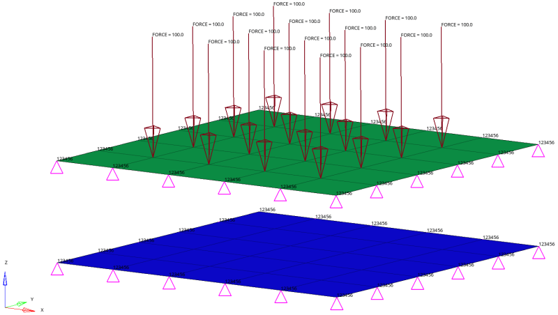
As it is my first doing contacts, I thought about making a simple model, two thin plates. One fixed and the other with a pressure and fixed at the edges. The idea is to make them enter in contact, only to understand how to set contacts in MSC Nastran (because there are too many cards : BCONTACT, BCTABL1, BCONECT, BCBODY, etc).
I am using HyperMesh as pre-processor. I leave an image attached of the model as well as the .bdf file.
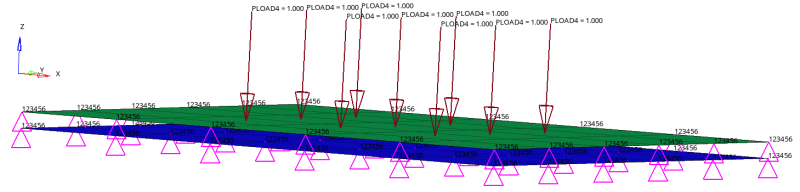
The model is quite simple, two plates with 25 elements each one. Material alu (E=78000MPa and nu=0.33), thickness = 0.1mm and the plates are separated 0.15mm. Uniform pressure applied of 5MPa.
The problem is that even if the model runs, I see the plate with the pressure penetrating the fixed one, and no contact is observed (cf. figure below).
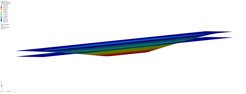
I would really apreciate if someone figures out what the problem might be.
The bdf file is attached and I also leave it next :
$$------------------------------------------------------------------------------$
$$ $
$$ NASTRAN Input Deck Generated by HyperMesh Version :2021.2.0.31
$$ Generated using HyperMesh-Nastran Template Version : 2021.2.0.31
$$ $
$$ Template: NastranMSC general $
$$ $
$$------------------------------------------------------------------------------$
$$------------------------------------------------------------------------------$
$$ Executive Control Cards $
$$------------------------------------------------------------------------------$
SOL 101
CEND
$$------------------------------------------------------------------------------$
$$ Case Control Cards $
$$------------------------------------------------------------------------------$
BCONTACT = 0
BOUTPUT(SORT1,PLOT) = ALL
DISPLACEMENT(SORT1,PRINT,REAL) = ALL
SPCFORCES(SORT1,PRINT,REAL) = ALL
STRESS(SORT1,PRINT,REAL,VONMISES,BILIN) = ALL
$
$HMNAME LOADSTEP 1"PRESSURE"
SUBCASE 1
SUBTITLE = PRESSURE
LABEL= PRESSURE
SPC = 2
LOAD = 4
ANALYSIS = STATICS
BCONTACT = 1
$$------------------------------------------------------------------------------$
$$ Bulk Data Cards $
$$------------------------------------------------------------------------------$
BEGIN BULK
PARAM,POST,1
PARAM,PRTMAXIM,YES
$$
$$ GRID Data
$$
GRID 1 1.5 1.5 0.0
GRID 2 1.5 0.5 0.0
GRID 3 1.5 -0.5 0.0
GRID 4 1.5 -1.5 0.0
GRID 5 0.5 1.5 0.0
GRID 6 0.5 0.5 0.0
GRID 7 0.5 -0.5 0.0
GRID 8 0.5 -1.5 0.0
GRID 9 -0.5 1.5 0.0
GRID 10 -0.5 0.5 0.0
GRID 11 -0.5 -0.5 0.0
GRID 12 -0.5 -1.5 0.0
GRID 13 -1.5 1.5 0.0
GRID 14 -1.5 0.5 0.0
GRID 15 -1.5 -0.5 0.0
GRID 16 -1.5 -1.5 0.0
GRID 17 2.5 1.5 0.0
GRID 18 2.5 0.5 0.0
GRID 19 2.5 -0.5 0.0
GRID 20 2.5 -1.5 0.0
GRID 21 -2.5 1.5 0.0
GRID 22 -2.5 0.5 0.0
GRID 23 -2.5 -0.5 0.0
GRID 24 -2.5 -1.5 0.0
GRID 25 2.5 2.5 0.0
GRID 26 2.5 -2.5 0.0
GRID 27 1.5 2.5 0.0
GRID 28 1.5 -2.5 0.0
GRID 29 0.5 2.5 0.0
GRID 30 0.5 -2.5 0.0
GRID 31 -0.5 2.5 0.0
GRID 32 -0.5 -2.5 0.0
GRID 33 -1.5 2.5 0.0
GRID 34 -1.5 -2.5 0.0
GRID 35 -2.5 2.5 0.0
GRID 36 -2.5 -2.5 0.0
GRID 37 1.5 1.5 -0.15
GRID 38 1.5 0.5 -0.15
GRID 39 1.5 -0.5 -0.15
GRID 40 1.5 -1.5 -0.15
GRID 41 0.5 1.5 -0.15
GRID 42 0.5 0.5 -0.15
GRID 43 0.5 -0.5 -0.15
GRID 44 0.5 -1.5 -0.15
GRID 45 -0.5 1.5 -0.15
GRID 46 -0.5 0.5 -0.15
GRID 47 -0.5 -0.5 -0.15
GRID 48 -0.5 -1.5 -0.15
GRID 49 -1.5 1.5 -0.15
GRID 50 -1.5 0.5 -0.15
GRID 51 -1.5 -0.5 -0.15
GRID 52 -1.5 -1.5 -0.15
GRID 53 2.5 1.5 -0.15
GRID 54 2.5 0.5 -0.15
GRID 55 2.5 -0.5 -0.15
GRID 56 2.5 -1.5 -0.15
GRID 57 -2.5 1.5 -0.15
GRID 58 -2.5 0.5 -0.15
GRID 59 -2.5 -0.5 -0.15
GRID 60 -2.5 -1.5 -0.15
GRID 61 2.5 2.5 -0.15
GRID 62 2.5 -2.5 -0.15
GRID 63 1.5 2.5 -0.15
GRID 64 1.5 -2.5 -0.15
GRID 65 0.5 2.5 -0.15
GRID 66 0.5 -2.5 -0.15
GRID 67 -0.5 2.5 -0.15
GRID 68 -0.5 -2.5 -0.15
GRID 69 -1.5 2.5 -0.15
GRID 70 -1.5 -2.5 -0.15
GRID 71 -2.5 2.5 -0.15
GRID 72 -2.5 -2.5 -0.15
$$
$$------------------------------------------------------------------------------$
$$ Group Definitions $
$$------------------------------------------------------------------------------$
$$
$$ CQUAD4 Elements
$$
$HMCOMP ID 1 1 4
CQUAD4 1 1 25 17 1 27
CQUAD4 2 1 17 18 2 1
CQUAD4 3 1 18 19 3 2
CQUAD4 4 1 19 20 4 3
CQUAD4 5 1 20 26 28 4
CQUAD4 6 1 27 1 5 29
CQUAD4 7 1 1 2 6 5
CQUAD4 8 1 2 3 7 6
CQUAD4 9 1 3 4 8 7
CQUAD4 10 1 4 28 30 8
CQUAD4 11 1 29 5 9 31
CQUAD4 12 1 5 6 10 9
CQUAD4 13 1 6 7 11 10
CQUAD4 14 1 7 8 12 11
CQUAD4 15 1 8 30 32 12
CQUAD4 16 1 31 9 13 33
CQUAD4 17 1 9 10 14 13
CQUAD4 18 1 10 11 15 14
CQUAD4 19 1 11 12 16 15
CQUAD4 20 1 12 32 34 16
CQUAD4 21 1 33 13 21 35
CQUAD4 22 1 13 14 22 21
CQUAD4 23 1 14 15 23 22
CQUAD4 24 1 15 16 24 23
CQUAD4 25 1 16 34 36 24
$HMCOMP ID 2 1 4
CQUAD4 26 1 61 53 37 63
CQUAD4 27 1 53 54 38 37
CQUAD4 28 1 54 55 39 38
CQUAD4 29 1 55 56 40 39
CQUAD4 30 1 56 62 64 40
CQUAD4 31 1 63 37 41 65
CQUAD4 32 1 37 38 42 41
CQUAD4 33 1 38 39 43 42
CQUAD4 34 1 39 40 44 43
CQUAD4 35 1 40 64 66 44
CQUAD4 36 1 65 41 45 67
CQUAD4 37 1 41 42 46 45
CQUAD4 38 1 42 43 47 46
CQUAD4 39 1 43 44 48 47
CQUAD4 40 1 44 66 68 48
CQUAD4 41 1 67 45 49 69
CQUAD4 42 1 45 46 50 49
CQUAD4 43 1 46 47 51 50
CQUAD4 44 1 47 48 52 51
CQUAD4 45 1 48 68 70 52
CQUAD4 46 1 69 49 57 71
CQUAD4 47 1 49 50 58 57
CQUAD4 48 1 50 51 59 58
CQUAD4 49 1 51 52 60 59
CQUAD4 50 1 52 70 72 60
$
$HMSET 1 2 "Top_Slave" 27
$HMSETTYPE 1 "regular" 27
BSURF 1 1 2 3 4 5 6 7
+ 8 9 10 11 12 13 14 15
+ 16 17 18 19 20 21 22 23
+ 24 25
$
$HMSET 2 2 "Down_Master" 27
$HMSETTYPE 2 "regular" 27
BSURF 2 50 49 48 47 46 45 44
+ 43 42 41 40 39 38 37 36
+ 35 34 33 32 31 30 29 28
+ 27 26
$$
$$------------------------------------------------------------------------------$
$$ HyperMesh name information for generic property collectors $
$$------------------------------------------------------------------------------$
$$
$$------------------------------------------------------------------------------$
$$ Property Definition for 1-D Elements $
$$------------------------------------------------------------------------------$
$$
$HMNAME GROUP 100"BCONECT" "BCONECT"
$HWCOLOR GROUP 100 29
BCONECT 100 2 1 2
$$
$$------------------------------------------------------------------------------$
$$ HyperMesh name and color information for generic components $
$$------------------------------------------------------------------------------$
$HMNAME COMP 1"Up_Slave" 1 "Plaque" 4
$HWCOLOR COMP 1 55
$
$HMNAME COMP 2"Down_Master" 1 "Plaque" 4
$HWCOLOR COMP 2 5
$
$$
$$------------------------------------------------------------------------------$
$$ Property Definition for Surface and Volume Elements $
$$------------------------------------------------------------------------------$
$$
$$ BCONPRG Data
$
$HMNAME PROP 2"BCONPRG_Geometric_Props" 6
$HWCOLOR PROP 2 24
BCONPRG 2 COPTM 11011COPTS 11011ICOORD 1
+ ISEARCH 1
$$
$$ PSHELL Data
$
$HMNAME PROP 1"Plaque" 4
$HWCOLOR PROP 1 7
PSHELL 1 1 0.1 1 1
$$
BCTABL1 1 100
$$
$$
BCBODY1 1 3D DEFORM 1
$$
BCBODY1 2 3D DEFORM 2
$$--------------------------------------------------------------
$$ HYPERMESH TAGS
$$--------------------------------------------------------------
$$BEGIN TAGS
$$END TAGS
$$
$$------------------------------------------------------------------------------$
$$ HyperMesh name information for generic materials $
$$------------------------------------------------------------------------------$
$$
$$------------------------------------------------------------------------------$
$$ Material Definition Cards $
$$------------------------------------------------------------------------------$
$$
$$ MAT1 Data
$
$HMNAME MAT 1"Alu" "MAT1"
$HWCOLOR MAT 1 6
MAT1 178000.0 0.33
$$
$$------------------------------------------------------------------------------$
$$ Loads and Boundary Conditions $
$$------------------------------------------------------------------------------$
$$
$$HyperMesh name and color information for generic loadcollectors
$$
$HMNAME LOADCOL 3"PRESSURE"
$HWCOLOR LOADCOL 3 20
$
$$
$$ SPC Data
$$
SPC 1 72 123456 0.0
SPC 1 71 123456 0.0
SPC 1 70 123456 0.0
SPC 1 69 123456 0.0
SPC 1 68 123456 0.0
SPC 1 67 123456 0.0
SPC 1 66 123456 0.0
SPC 1 65 123456 0.0
SPC 1 64 123456 0.0
SPC 1 63 123456 0.0
SPC 1 62 123456 0.0
SPC 1 61 123456 0.0
SPC 1 60 123456 0.0
SPC 1 59 123456 0.0
SPC 1 58 123456 0.0
SPC 1 57 123456 0.0
SPC 1 56 123456 0.0
SPC 1 55 123456 0.0
SPC 1 54 123456 0.0
SPC 1 53 123456 0.0
SPC 1 52 123456 0.0
SPC 1 51 123456 0.0
SPC 1 50 123456 0.0
SPC 1 49 123456 0.0
SPC 1 48 123456 0.0
SPC 1 47 123456 0.0
SPC 1 46 123456 0.0
SPC 1 45 123456 0.0
SPC 1 44 123456 0.0
SPC 1 43 123456 0.0
SPC 1 42 123456 0.0
SPC 1 41 123456 0.0
SPC 1 40 123456 0.0
SPC 1 39 123456 0.0
SPC 1 38 123456 0.0
SPC 1 37 123456 0.0
SPC 1 17 123456 0.0
SPC 1 18 123456 0.0
SPC 1 19 123456 0.0
SPC 1 20 123456 0.0
SPC 1 21 123456 0.0
SPC 1 22 123456 0.0
SPC 1 23 123456 0.0
SPC 1 24 123456 0.0
SPC 1 25 123456 0.0
SPC 1 26 123456 0.0
SPC 1 27 123456 0.0
SPC 1 28 123456 0.0
SPC 1 29 123456 0.0
SPC 1 30 123456 0.0
SPC 1 31 123456 0.0
SPC 1 32 123456 0.0
SPC 1 33 123456 0.0
SPC 1 34 123456 0.0
SPC 1 35 123456 0.0
SPC 1 36 123456 0.0
$$
$$ PLOAD4 Data
$$
PLOAD4 3 7 1.0
PLOAD4 3 8 1.0
PLOAD4 3 9 1.0
PLOAD4 3 12 1.0
PLOAD4 3 13 1.0
PLOAD4 3 14 1.0
PLOAD4 3 17 1.0
PLOAD4 3 18 1.0
PLOAD4 3 19 1.0
$$
$$ LOAD cards
$$
$HMNAME LOADCOL 4"LOAD"
$HWCOLOR LOADCOL 4 21
$$
LOAD 4 1.0 5.0 3
$
$$
$$ BCPARA cards
$$
$HMNAME LOADCOL 5"BCPARA"
$HWCOLOR LOADCOL 5 33
BCPARA 0LINCNT 1METHOD NODESURF
$$
$$
$$ SPCADD cards
$$
$HMNAME LOADCOL 2"SPCADD"
$HWCOLOR LOADCOL 2 17
$$
SPCADD 2 1
$
ENDDATA
Thanks in advance !
Sincerely,
EC
I come to your help because I have tried everything and I cannot make a simple contact work on Nastran.
As it is my first doing contacts, I thought about making a simple model, two thin plates. One fixed and the other with a pressure and fixed at the edges. The idea is to make them enter in contact, only to understand how to set contacts in MSC Nastran (because there are too many cards : BCONTACT, BCTABL1, BCONECT, BCBODY, etc).
I am using HyperMesh as pre-processor. I leave an image attached of the model as well as the .bdf file.
The model is quite simple, two plates with 25 elements each one. Material alu (E=78000MPa and nu=0.33), thickness = 0.1mm and the plates are separated 0.15mm. Uniform pressure applied of 5MPa.
The problem is that even if the model runs, I see the plate with the pressure penetrating the fixed one, and no contact is observed (cf. figure below).
I would really apreciate if someone figures out what the problem might be.
The bdf file is attached and I also leave it next :
$$------------------------------------------------------------------------------$
$$ $
$$ NASTRAN Input Deck Generated by HyperMesh Version :2021.2.0.31
$$ Generated using HyperMesh-Nastran Template Version : 2021.2.0.31
$$ $
$$ Template: NastranMSC general $
$$ $
$$------------------------------------------------------------------------------$
$$------------------------------------------------------------------------------$
$$ Executive Control Cards $
$$------------------------------------------------------------------------------$
SOL 101
CEND
$$------------------------------------------------------------------------------$
$$ Case Control Cards $
$$------------------------------------------------------------------------------$
BCONTACT = 0
BOUTPUT(SORT1,PLOT) = ALL
DISPLACEMENT(SORT1,PRINT,REAL) = ALL
SPCFORCES(SORT1,PRINT,REAL) = ALL
STRESS(SORT1,PRINT,REAL,VONMISES,BILIN) = ALL
$
$HMNAME LOADSTEP 1"PRESSURE"
SUBCASE 1
SUBTITLE = PRESSURE
LABEL= PRESSURE
SPC = 2
LOAD = 4
ANALYSIS = STATICS
BCONTACT = 1
$$------------------------------------------------------------------------------$
$$ Bulk Data Cards $
$$------------------------------------------------------------------------------$
BEGIN BULK
PARAM,POST,1
PARAM,PRTMAXIM,YES
$$
$$ GRID Data
$$
GRID 1 1.5 1.5 0.0
GRID 2 1.5 0.5 0.0
GRID 3 1.5 -0.5 0.0
GRID 4 1.5 -1.5 0.0
GRID 5 0.5 1.5 0.0
GRID 6 0.5 0.5 0.0
GRID 7 0.5 -0.5 0.0
GRID 8 0.5 -1.5 0.0
GRID 9 -0.5 1.5 0.0
GRID 10 -0.5 0.5 0.0
GRID 11 -0.5 -0.5 0.0
GRID 12 -0.5 -1.5 0.0
GRID 13 -1.5 1.5 0.0
GRID 14 -1.5 0.5 0.0
GRID 15 -1.5 -0.5 0.0
GRID 16 -1.5 -1.5 0.0
GRID 17 2.5 1.5 0.0
GRID 18 2.5 0.5 0.0
GRID 19 2.5 -0.5 0.0
GRID 20 2.5 -1.5 0.0
GRID 21 -2.5 1.5 0.0
GRID 22 -2.5 0.5 0.0
GRID 23 -2.5 -0.5 0.0
GRID 24 -2.5 -1.5 0.0
GRID 25 2.5 2.5 0.0
GRID 26 2.5 -2.5 0.0
GRID 27 1.5 2.5 0.0
GRID 28 1.5 -2.5 0.0
GRID 29 0.5 2.5 0.0
GRID 30 0.5 -2.5 0.0
GRID 31 -0.5 2.5 0.0
GRID 32 -0.5 -2.5 0.0
GRID 33 -1.5 2.5 0.0
GRID 34 -1.5 -2.5 0.0
GRID 35 -2.5 2.5 0.0
GRID 36 -2.5 -2.5 0.0
GRID 37 1.5 1.5 -0.15
GRID 38 1.5 0.5 -0.15
GRID 39 1.5 -0.5 -0.15
GRID 40 1.5 -1.5 -0.15
GRID 41 0.5 1.5 -0.15
GRID 42 0.5 0.5 -0.15
GRID 43 0.5 -0.5 -0.15
GRID 44 0.5 -1.5 -0.15
GRID 45 -0.5 1.5 -0.15
GRID 46 -0.5 0.5 -0.15
GRID 47 -0.5 -0.5 -0.15
GRID 48 -0.5 -1.5 -0.15
GRID 49 -1.5 1.5 -0.15
GRID 50 -1.5 0.5 -0.15
GRID 51 -1.5 -0.5 -0.15
GRID 52 -1.5 -1.5 -0.15
GRID 53 2.5 1.5 -0.15
GRID 54 2.5 0.5 -0.15
GRID 55 2.5 -0.5 -0.15
GRID 56 2.5 -1.5 -0.15
GRID 57 -2.5 1.5 -0.15
GRID 58 -2.5 0.5 -0.15
GRID 59 -2.5 -0.5 -0.15
GRID 60 -2.5 -1.5 -0.15
GRID 61 2.5 2.5 -0.15
GRID 62 2.5 -2.5 -0.15
GRID 63 1.5 2.5 -0.15
GRID 64 1.5 -2.5 -0.15
GRID 65 0.5 2.5 -0.15
GRID 66 0.5 -2.5 -0.15
GRID 67 -0.5 2.5 -0.15
GRID 68 -0.5 -2.5 -0.15
GRID 69 -1.5 2.5 -0.15
GRID 70 -1.5 -2.5 -0.15
GRID 71 -2.5 2.5 -0.15
GRID 72 -2.5 -2.5 -0.15
$$
$$------------------------------------------------------------------------------$
$$ Group Definitions $
$$------------------------------------------------------------------------------$
$$
$$ CQUAD4 Elements
$$
$HMCOMP ID 1 1 4
CQUAD4 1 1 25 17 1 27
CQUAD4 2 1 17 18 2 1
CQUAD4 3 1 18 19 3 2
CQUAD4 4 1 19 20 4 3
CQUAD4 5 1 20 26 28 4
CQUAD4 6 1 27 1 5 29
CQUAD4 7 1 1 2 6 5
CQUAD4 8 1 2 3 7 6
CQUAD4 9 1 3 4 8 7
CQUAD4 10 1 4 28 30 8
CQUAD4 11 1 29 5 9 31
CQUAD4 12 1 5 6 10 9
CQUAD4 13 1 6 7 11 10
CQUAD4 14 1 7 8 12 11
CQUAD4 15 1 8 30 32 12
CQUAD4 16 1 31 9 13 33
CQUAD4 17 1 9 10 14 13
CQUAD4 18 1 10 11 15 14
CQUAD4 19 1 11 12 16 15
CQUAD4 20 1 12 32 34 16
CQUAD4 21 1 33 13 21 35
CQUAD4 22 1 13 14 22 21
CQUAD4 23 1 14 15 23 22
CQUAD4 24 1 15 16 24 23
CQUAD4 25 1 16 34 36 24
$HMCOMP ID 2 1 4
CQUAD4 26 1 61 53 37 63
CQUAD4 27 1 53 54 38 37
CQUAD4 28 1 54 55 39 38
CQUAD4 29 1 55 56 40 39
CQUAD4 30 1 56 62 64 40
CQUAD4 31 1 63 37 41 65
CQUAD4 32 1 37 38 42 41
CQUAD4 33 1 38 39 43 42
CQUAD4 34 1 39 40 44 43
CQUAD4 35 1 40 64 66 44
CQUAD4 36 1 65 41 45 67
CQUAD4 37 1 41 42 46 45
CQUAD4 38 1 42 43 47 46
CQUAD4 39 1 43 44 48 47
CQUAD4 40 1 44 66 68 48
CQUAD4 41 1 67 45 49 69
CQUAD4 42 1 45 46 50 49
CQUAD4 43 1 46 47 51 50
CQUAD4 44 1 47 48 52 51
CQUAD4 45 1 48 68 70 52
CQUAD4 46 1 69 49 57 71
CQUAD4 47 1 49 50 58 57
CQUAD4 48 1 50 51 59 58
CQUAD4 49 1 51 52 60 59
CQUAD4 50 1 52 70 72 60
$
$HMSET 1 2 "Top_Slave" 27
$HMSETTYPE 1 "regular" 27
BSURF 1 1 2 3 4 5 6 7
+ 8 9 10 11 12 13 14 15
+ 16 17 18 19 20 21 22 23
+ 24 25
$
$HMSET 2 2 "Down_Master" 27
$HMSETTYPE 2 "regular" 27
BSURF 2 50 49 48 47 46 45 44
+ 43 42 41 40 39 38 37 36
+ 35 34 33 32 31 30 29 28
+ 27 26
$$
$$------------------------------------------------------------------------------$
$$ HyperMesh name information for generic property collectors $
$$------------------------------------------------------------------------------$
$$
$$------------------------------------------------------------------------------$
$$ Property Definition for 1-D Elements $
$$------------------------------------------------------------------------------$
$$
$HMNAME GROUP 100"BCONECT" "BCONECT"
$HWCOLOR GROUP 100 29
BCONECT 100 2 1 2
$$
$$------------------------------------------------------------------------------$
$$ HyperMesh name and color information for generic components $
$$------------------------------------------------------------------------------$
$HMNAME COMP 1"Up_Slave" 1 "Plaque" 4
$HWCOLOR COMP 1 55
$
$HMNAME COMP 2"Down_Master" 1 "Plaque" 4
$HWCOLOR COMP 2 5
$
$$
$$------------------------------------------------------------------------------$
$$ Property Definition for Surface and Volume Elements $
$$------------------------------------------------------------------------------$
$$
$$ BCONPRG Data
$
$HMNAME PROP 2"BCONPRG_Geometric_Props" 6
$HWCOLOR PROP 2 24
BCONPRG 2 COPTM 11011COPTS 11011ICOORD 1
+ ISEARCH 1
$$
$$ PSHELL Data
$
$HMNAME PROP 1"Plaque" 4
$HWCOLOR PROP 1 7
PSHELL 1 1 0.1 1 1
$$
BCTABL1 1 100
$$
$$
BCBODY1 1 3D DEFORM 1
$$
BCBODY1 2 3D DEFORM 2
$$--------------------------------------------------------------
$$ HYPERMESH TAGS
$$--------------------------------------------------------------
$$BEGIN TAGS
$$END TAGS
$$
$$------------------------------------------------------------------------------$
$$ HyperMesh name information for generic materials $
$$------------------------------------------------------------------------------$
$$
$$------------------------------------------------------------------------------$
$$ Material Definition Cards $
$$------------------------------------------------------------------------------$
$$
$$ MAT1 Data
$
$HMNAME MAT 1"Alu" "MAT1"
$HWCOLOR MAT 1 6
MAT1 178000.0 0.33
$$
$$------------------------------------------------------------------------------$
$$ Loads and Boundary Conditions $
$$------------------------------------------------------------------------------$
$$
$$HyperMesh name and color information for generic loadcollectors
$$
$HMNAME LOADCOL 3"PRESSURE"
$HWCOLOR LOADCOL 3 20
$
$$
$$ SPC Data
$$
SPC 1 72 123456 0.0
SPC 1 71 123456 0.0
SPC 1 70 123456 0.0
SPC 1 69 123456 0.0
SPC 1 68 123456 0.0
SPC 1 67 123456 0.0
SPC 1 66 123456 0.0
SPC 1 65 123456 0.0
SPC 1 64 123456 0.0
SPC 1 63 123456 0.0
SPC 1 62 123456 0.0
SPC 1 61 123456 0.0
SPC 1 60 123456 0.0
SPC 1 59 123456 0.0
SPC 1 58 123456 0.0
SPC 1 57 123456 0.0
SPC 1 56 123456 0.0
SPC 1 55 123456 0.0
SPC 1 54 123456 0.0
SPC 1 53 123456 0.0
SPC 1 52 123456 0.0
SPC 1 51 123456 0.0
SPC 1 50 123456 0.0
SPC 1 49 123456 0.0
SPC 1 48 123456 0.0
SPC 1 47 123456 0.0
SPC 1 46 123456 0.0
SPC 1 45 123456 0.0
SPC 1 44 123456 0.0
SPC 1 43 123456 0.0
SPC 1 42 123456 0.0
SPC 1 41 123456 0.0
SPC 1 40 123456 0.0
SPC 1 39 123456 0.0
SPC 1 38 123456 0.0
SPC 1 37 123456 0.0
SPC 1 17 123456 0.0
SPC 1 18 123456 0.0
SPC 1 19 123456 0.0
SPC 1 20 123456 0.0
SPC 1 21 123456 0.0
SPC 1 22 123456 0.0
SPC 1 23 123456 0.0
SPC 1 24 123456 0.0
SPC 1 25 123456 0.0
SPC 1 26 123456 0.0
SPC 1 27 123456 0.0
SPC 1 28 123456 0.0
SPC 1 29 123456 0.0
SPC 1 30 123456 0.0
SPC 1 31 123456 0.0
SPC 1 32 123456 0.0
SPC 1 33 123456 0.0
SPC 1 34 123456 0.0
SPC 1 35 123456 0.0
SPC 1 36 123456 0.0
$$
$$ PLOAD4 Data
$$
PLOAD4 3 7 1.0
PLOAD4 3 8 1.0
PLOAD4 3 9 1.0
PLOAD4 3 12 1.0
PLOAD4 3 13 1.0
PLOAD4 3 14 1.0
PLOAD4 3 17 1.0
PLOAD4 3 18 1.0
PLOAD4 3 19 1.0
$$
$$ LOAD cards
$$
$HMNAME LOADCOL 4"LOAD"
$HWCOLOR LOADCOL 4 21
$$
LOAD 4 1.0 5.0 3
$
$$
$$ BCPARA cards
$$
$HMNAME LOADCOL 5"BCPARA"
$HWCOLOR LOADCOL 5 33
BCPARA 0LINCNT 1METHOD NODESURF
$$
$$
$$ SPCADD cards
$$
$HMNAME LOADCOL 2"SPCADD"
$HWCOLOR LOADCOL 2 17
$$
SPCADD 2 1
$
ENDDATA
Thanks in advance !
Sincerely,
EC
![[smile]](/data/assets/smilies/smile.gif "[smile] [smile]") .
.