I have worked since a while in the ‘’Abaqus’’ FEM model developed in ‘’ Prediction of Residual Stresses after Laser-assisted Machining of Inconel 718 Using SPH ’’.
Although model description seems to be clearly simple, the model steel not working. I try to sum à rise a brief description of the model
[highlight #FCE94F]Inconel-718[/highlight]
Conductivity 44
Density 1.28E-8
Elastic (Shear Modulus ) 80769
Specific Heat 435000000
Plastic A=1241 ; B=622 C=0.0134 n=0.6522 m=1.3 RefplasticStrain=1 MeltingTemp=1600 Transition Temp=293
Mie-Gruneisen EOS type Us-Up C0=4578 s=1.33 Gamma0=1.67
[highlight #FCE94F]Substrat_WCCo[/highlight]
Conductivity 80
Density 1.5E-008
Elastic Young=800000 Poisson=0.23
Expansion 4.5E-6
Specific Heat 203000000
2- Step procedure : Dynamic,Temp-dip,Explicit (step time=0.001)
3- The contact between the workpiece and tool was defined using general contact not with node-to-surface contact algorithm
-Tangential Behavior (Penalty)
Friction coef =0.2
-Thermal conductance
Conductance / Clrearance line1 : 10000000/0 line 2: 0/0.001
-Heat Gneration
Fraction of dissipated energy caused by friction : Default
Fraction of converted heat distributed to slave surface : 61%
4- The tool is modeled with Coupled temperature-displacement Tet C3D4T elementsand the workpiece with 3D stress Hex (conversion To particles , coteron : time , Threshold : 0. ,PPD :1 , Kernel : Cubic , )
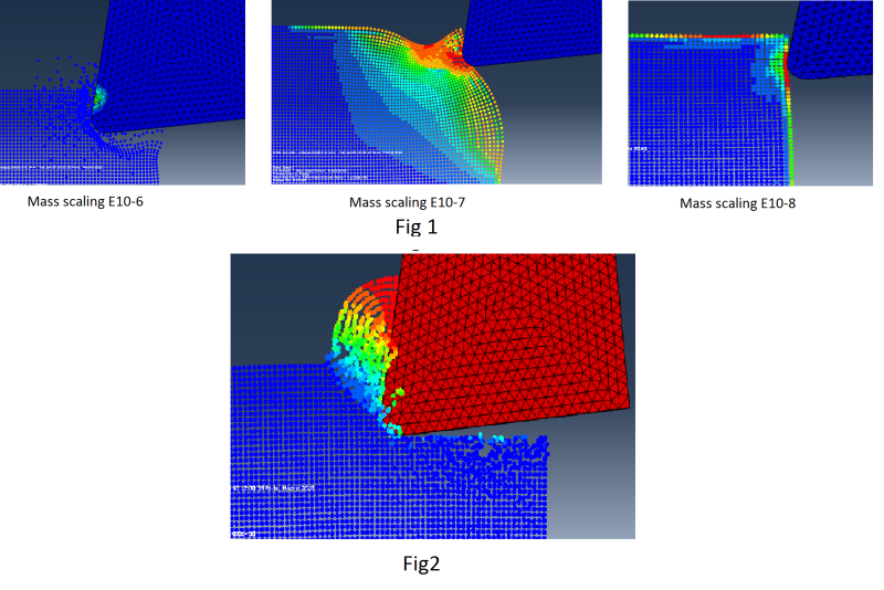
As you can see from Fig 1, the change in mass scaling can affect the chip forming process, but none of these 3 cases can be accepted as a solution
also with a mass scaling 10E-7 and C0=4578E3 Mie-Gruneisen EOS parameter fig2 (This change is not justified a problem of unit) but the chip is generated (even in this case the model diverges).
I would be highly grateful if any one can help me to detect the problem with this model and to present a much more accurated and detailed description in node-to-surface contact algorithm considered in this work

