Continue to Site

Eng-Tips is the largest engineering community on the Internet

Intelligent Work Forums for Engineering Professionals

  • Congratulations MintJulep on being selected by the Eng-Tips community for having the most helpful posts in the forums last week. Way to Go!

Continuous Beam Connection - HSS Columns 5

Status
Not open for further replies.

CFurt

Structural
Oct 6, 2023
2
Hello all,

Been visiting these forums for years on various topics over my engineering path, first time poster.
I've had something similar to this come up a few times now, and is becoming more common, of W-shape continuous beams over HSS posts.

I have a project, with continuous W-shape beams over HSS columns, with fully welded connections.
First look over, I told the designer these would be moment connections, and that the HSS likely wouldn't support the moment transferred. (Connections look almost exactly like the typicals demonstrated in AISC Manual and HSS Connections book for moment connections).
When I suggested bolted connections, response I got was basically that this is the preferred method in the area and is how they/engineers have been doing it in the past.
I guess just looking for a confirmation that I'm not crazy in that this would transfer moments from the continuous beam.

In terms of perspective, first continuous beam investigated (interior, just floor loading) has about 55kip and 92kip-ft moment at center post (W14x68 beam and HSS6x6x5/16 call-outs).

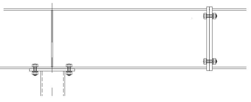
Lower Detail in attachment also shows 2 separate beams bearing on post/plate assembly, with the ends welded together, which I have yet to see before and don't like the look of, with stiffner plate out 2". In my mind I'm thinking load is directed out and kind of in no-man's land, but don't know if I'm splitting hairs at this point.

Looking for thoughts/opinions on this. Have been down the rabbit hole on previous jobs recently regarding pinned vs moment connection, or how close to which it is, for W-shape bearing over top of HSS posts.

Either way, for a mark-up I was thinking about just sizing the columns to take the moment transfer (and correcting connection details a bit).

Thank you, and thanks to all the help I've found from the usual names I've seen over the past handful of years!
- CFurt



 https://files.engineering.com/getfile.aspx?folder=d832a45c-5a5d-454b-ac5b-7b2fd3799503&file=Connections.png
Replies continue below

Recommended for you

I've never seen a stacked column or cap plate welded to the beam like that. All that field welding seems very disadvantageous. I have always seen bolted ones like you mentioned.

The plate is pretty thin, so I would not expect it to have much strength to transfer moment.
 
I've done a moment connection here once or twice, the issue is the HSS offers little deflection control (due to low stiffness), and you get a lot of drift.

Your issue is the HSS won't have much moment capacity, which is a separate issue, and transferring the moment into the HSS. It won't be structurally efficient, though, but that's not always what people want. A through column with side plate connections to the beams would be more conventional. Fewer pieces, less field welding.
 
So what exactly is this detail trying to achieve?

On the top detail - the beam is already a through-moment entity so all that welding appears to be an attempt to make the column fully moment-capable in the overall connection, right?

The fillet weld symbols are backwards by the way - vertical on the triangle is always on the left per AWS standards.

Also - the "all-around" weld circle is inappropriate on the cap-plate-to-beam weld unless the plate is narrower than the beam flange width.

The lower detail appears to show two separate beams but the top flange has no continuity across the top - so not a moment connection.


I'd have to look into a connection with a column over it and how the capacity of the connection could be reduced by the compression load. For the continuous beam over the column, I'd use a detail similar to attached. A single stiffener plate, not to transfer load but to maintain the stability of the section for the first plastic hinge to form. Splices are typically located at the inflection point for the 'plastic moment BMD', and have to be able to accommodate the moment developed for any alternate loading. Code stipulates a minimum of 25% of the section plastic moment capacity. Also use plastic section modulus for all moment calculations... gives you an added 10% moment capacity (generally). Other than increasing the splice moment, alternate loading does not affect the beam sizes.

Plastic_Design_Connection_sialbh.png


My $.02... Where appropriate, I've used this type of design for 50 years... Splice connection is for Vf and Mf (design). HS bolts are OK for shear, but great for tension. This connection is used in conjunction with X bracing... not moment frame.

-----*****-----
So strange to see the singularity approaching while the entire planet is rapidly turning into a hellscape. -John Coates

-Dik
 
I like dik's detail, except that I usually use for a stiffener, two half HSS sections shop welded to the beam.
 
Two stiffeners always seems like too much (I mean one each side of the HSS, so "four" if you want to count it that way). If you presume all of the force comes into the HSS from the stiffener, there's a check for the HSS wall you can do for a concentrated force, as I recall, to give yourself some comfort it works.
 
Two HSS half sections is a little more pricey and usually web crippling isn't an issue. As I noted, the purpose of the web stiffener is to maintain the section at the location of the first plastic hinge. Most web stiffeners I run up to within a couple of inches of the top flange. With plastic design, I run them all the way up... Two HSS half sections works...

A bit of an anecdote with this... About 50 years back, I did a large warehouse for one of my profs at university. He was suspended by the association and I took over the work he was doing. After I did it, he asked why I hadn't used plastic design and he explained the methodology... After that, I picked up a couple of good texts on plastic design... Massonette and Save and Baker's Steel Skeleton. I re-did the work and there was quite a savings. I had heard that people didn't use plastic design because it was more expensive (a total myth). A similar comment about HSS columns back then... It turned out (at the time) if columns were greater than about 12' or so, they were less costly than W sections. This was way back when I was a 'real' rookie.

Another anecdote, from back then. A contractor had a strip of plywood in a concrete slab on grade and asked if he should remove it... I told him not to bother, that the concrete would shrink and it would be easy to pull it out... If the slab still exists, the plywood is likely still there.

-----*****-----
So strange to see the singularity approaching while the entire planet is rapidly turning into a hellscape. -John Coates

-Dik
 

They are generally not for load... Even with non-plastic design I still use stiffeners just to enhance the residual strength. I had a recent project where the EOR wanted a moment connection for a W18x71 beam was too low... (simple span, not plastic design).

Clipboard01_xw0yhy.jpg


The EOR confirmed the load was adequate... the splice I did was capable of resisting about 150 K-ft.

-----*****-----
So strange to see the singularity approaching while the entire planet is rapidly turning into a hellscape. -John Coates

-Dik
 
When I run a beam through a WF column, I use plate stiffeners each side of the web, under each flange. The split HSS is attempting to do something similar with HSS columns, but I agree it may be a bit of overkill.
 
It works... and is safe... good engineering, IMHO.

-----*****-----
So strange to see the singularity approaching while the entire planet is rapidly turning into a hellscape. -John Coates

-Dik
 
Thank you all for your time and inputs! Good info all around

Yea, these details are odd and going to have discussions with them with exactly what they are looking to achieve at the different connection scenarios.
The splice connection method is good to know, as I've personally never had to design steel beam splice before. The detail with splice over top of column I don't think is for overall beam length (less than 30ft overall), I think they might've decided to try and save a bit maybe with different beam sizes, not sure.

I'm going to suggest singular column through the floors and beams mounted at the sides, as proposed method and move from there. Savings pretty much on all sides I would imagine. Plus, the large upsize wouldn't fit in the walls/layout anyways. Personally, I never really saw an issue with installing 20ft or 30ft interior steel columns with this type of custom home construction; HSS6x4 is not very large compared to 30ft+ x68 beams at same jobsite and levels, but some builders have complained about that.

Thanks again!
- CFurt

- steeltubeinstitute site is good, have used that same article in the past.
 

Is generally a bad idea... this is likely the maximum design moment.

-----*****-----
So strange to see the singularity approaching while the entire planet is rapidly turning into a hellscape. -John Coates

-Dik
 
Beams, in general can be longer... my approach with a single splice is doable in most areas.

-----*****-----
So strange to see the singularity approaching while the entire planet is rapidly turning into a hellscape. -John Coates

-Dik
 
Status
Not open for further replies.

Part and Inventory Search

Sponsor