Continue to Site

Eng-Tips is the largest engineering community on the Internet

Intelligent Work Forums for Engineering Professionals

  • Congratulations KootK on being selected by the Eng-Tips community for having the most helpful posts in the forums last week. Way to Go!

Continuous beam on multiple closely spaced rollers 2

kaffy

Mechanical
Jun 2, 2020
190
Good Morning Fellow Engineers,

I have a beam with multiple closely spaced roller supports (shown only 4 in attached pdf but I have 12 in total) and a cantilever at one end. Design intent is to move the beam on rollers with hydraulic cylinder on one end. When I try to calculate the reaction loads using any beam calculator, it shows alternating reaction load directions and unusually high values that don’t seem accurate. Any tips on how to analyze a beam in situation like this?

Thank you
 

Attachments

  • Roller Support Setup.pdf
    19.2 KB · Views: 22
Replies continue below

Recommended for you

That makes complete sense if you supports are infinitely rigid which is presumably what you have modelled.

Fix your model use appropriate boundary conditions. ie; model in the actual stiffness of the supports or an estimate.

(We had a similar question last week where the user wasn't using appropriate boundary conditions. Though at least you've clearly caught the error and asking the question.)
INFINITELY RIGID:
1734634575928.png
SOME SUPPORT DEFLECTION (<1mm at all supports.)
1734634768842.png
 
Last edited:
That makes complete sense if you sup
Thank you very much. One last question: I understand that every connection is unique and will have a different stiffness value, but are there any standard reference values or general guidelines to use for those situations?
 
If your rollers can only support downward loads, then you model is wrong. Release the supports that have an uplift and see what you get.
 
That makes complete sense if you supports are infinitely rigid which is presumably what you have modelled.

Fix your model use appropriate boundary conditions. ie; model in the actual stiffness of the supports or an estimate.

(We had a similar question last week where the user wasn't using appropriate boundary conditions. Though at least you've clearly caught the error and asking the question.)
INFINITELY RIGID:
View attachment 2570
SOME SUPPORT DEFLECTION (<1mm at all supports.)
View attachment 2571
What's an appropriate way to estimate support stiffness to get a more accurate representation of what's going on?
 
Obviously you will need to include the beam's self-weight if you "release the supports that have an uplift".
 
Thank you very much. One last question: I understand that every connection is unique and will have a different stiffness value, but are there any standard reference values or general guidelines to use for those situations?

What's an appropriate way to estimate support stiffness to get a more accurate representation of what's going on?

Good engineering judgment is a start. If necessary calculations. The results aren't highly sensitive to the stiffness value. You can vary the stiffence by two orders of magnitude (x100) and only get variance in the highest reaction of 3x.

Meanwhile you should have a good estimation of the expected deflection based on the stiffness of the supports. Do you expect 4mm of movement? 0.4mm? or 0.04mm?


What you can guarantee is that your supports ARE NOT infinitely rigid, so start improving on that incorrect assumption.
So if I ran some columns with outriggers moment connected off, say for a crane rail, and found that the outrigger deflected 3mm. When analyzing the crane beam, do I just play around with the kN/mm stiffness until my beam model has that support deflecting 3mm? Since the reaction changes depending on support stiffness (although not much as you have eluded to) is it an iterative process whereby you guess an initial stiffness, check support deflection and re-analyze or is there a more straightforward way.
 
As an example lets assume that beyond the outrigger-column joint the column end conditions can be idealized as pinned and that the rigidity of the connection itself is not considered, then as an example:
20 ft tall W8x10 column
Outrigger located at mid height

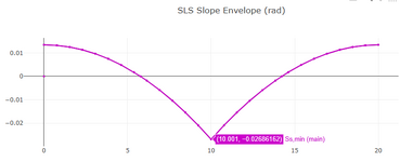
Applying and arbitrary moment of 100 ft-kips to column it yields a rotation at the load point of -0.02686162 rad.
1734710133359.png
1734710156208.png

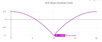
Assuming linear-elastic material the moment needed to make the rotation equal to 1 rad = 100 ft-kips / 0.02686162 rad = 3722.783 ft-kips/rad
1734710283933.png

So if looking at the outrigger as an isolated cantilever beam you would assign a rotational spring stiffness of 3722.783 ft-kips/rad

You could also do a vertical spring which can be derived for the column by equating PL/AE = 1 in or ft depending on the unit consistency needed.
 
In the beam problem proposed here by @kaffy I'm of the opinion that flexible supports are less important than specifying unidirectional compression only supports as I imagine the beam is simply laid down on top of the rollers with no positive attachment.

should qualify this as in context of the beam, if the reactions on the rollers is critical then a spring model should be used as the frontward rollers will all experience some compression, the rigid compression only model would tend to put all the reaction forces in at the last roller and clamped beam end at the piston. If it's not clamped at the piston then see @Denial response you'll need enough beam weight to counteract the outrigger force.
 
Last edited:
So if I ran some columns with outriggers moment connected off, say for a crane rail, and found that the outrigger deflected 3mm. When analyzing the crane beam, do I just play around with the kN/mm stiffness until my beam model has that support deflecting 3mm? Since the reaction changes depending on support stiffness (although not much as you have eluded to) is it an iterative process whereby you guess an initial stiffness, check support deflection and re-analyze or is there a more straightforward way.
You aren't looking at the deflection of your beam you are looking at the deflection of your supports.

This is a boundary condition problem, so examine your boundary conditions.
 
You aren't looking at the deflection of your beam you are looking at the deflection of your supports.

This is a boundary condition problem, so examine your boundary conditions.
Sorry, I mean the crane beam is sitting on the outriggers, so the outriggers are my support. Assume they are two separate models and not run in 3D for arguments sake.
 
Sorry, I mean the crane beam is sitting on the outriggers, so the outriggers are my support. Assume they are two separate models and not run in 3D for arguments sake.
Ok. I get it now. Sorry it wasn't clear to me what you were describing.

So if I ran some columns with outriggers moment connected off, say for a crane rail, and found that the outrigger deflected 3mm. When analyzing the crane beam, do I just play around with the kN/mm stiffness until my beam model has that support deflecting 3mm? Since the reaction changes depending on support stiffness (although not much as you have eluded to) is it an iterative process whereby you guess an initial stiffness, check support deflection and re-analyze or is there a more straightforward way.
If you were running it with two separate models then you could do this. You wouldn't need to play around with the kN/mm stiffness you could directly calculate it. If the outrigger deflectect 3mm when you had 100kN on it then you know the stiffness is 33.3kN/mm.

But that might be unnecessary depending on the crane rails design.
If it is simply supported then it is statically determinate, so the stiffness of the boundary conditions is irrelevant in the beam system behaviour. If the crane beam is continuous with differently identical spans the stiffness of the supports will almost be irrelevant too. If you have significantly varying spans it change things some what but again I wouldn't expect significant changes unless things are very weird.

Most of the time we can get away with simple boundary conditions, eg infinitely rigid or pinned non translational supports in out 2D/3D frame analysis. But when we have highly indeterminate structures we can get problems. In both this example and THIS PREVIOUS FORUM QUESTION example the supports were extremely close together which created a situation where small stiffness changes in the support would (or connection slop) have a big difference.

I have a such a scenario sitting on my to do list at the moment:
1734723458878.png


If you model that new beam on its own with rigid supports you will get reversing reaction as the beam is continue over the supports closest to the load. If instead you model it with springs for support or model in 3D the existing joists then you won't get reversing reactions. Instead you get load sharing between the 4 joists. Which is the intended purpose of this configuration.
 

Part and Inventory Search

Sponsor