Hi,
I have a question with regards to clarifying intent using <CF> when there are multiple surfaces of the same size.
I've marked up what I want to say, and was looking for help on what would be the best (clearest, least ambiguous, lowest chance for misinterpretation) way to specify this.
Essentially, what I'm looking to call out is:
[ul]
[li]Blue surfaces - 2X, not continuous[/li]
[li]Green surfaces - 2X, continuous feature, but not continuous to yellow surfaces[/li]
[li]Yellow surfaces - 2X, continuous feature, but not continuous to green surfaces[/li]
[/ul]
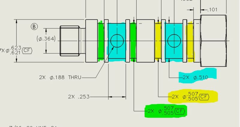
I realized even with adding the instance count, there is still ambiguity as to which surfaces are continuous to each other.
For example, I could interpret that dimensioning scheme in the following way, which would not give me the desired result.
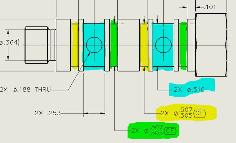
I was thinking of adding a label to each CF dimension and using a balloon to make it clear which is which.
Something like this:
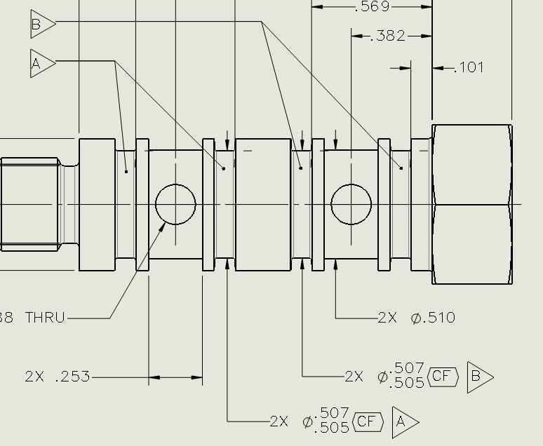
Before committing to this idea, I wanted to run this by some of the experts on this forum and see how you would handle this requirement.
For what its worth, the overall runout between all features is controlled by a note, and I really don't expect there to ever be any runout issues with these features from the normal machining process (single setup turned part) but, having spent enough years on the production floor as a manufacturing engineer, I know what can happen with rework, etc. and I just want to make sure that all requirements are crystal clear.
Thanks!
I have a question with regards to clarifying intent using <CF> when there are multiple surfaces of the same size.
I've marked up what I want to say, and was looking for help on what would be the best (clearest, least ambiguous, lowest chance for misinterpretation) way to specify this.
Essentially, what I'm looking to call out is:
[ul]
[li]Blue surfaces - 2X, not continuous[/li]
[li]Green surfaces - 2X, continuous feature, but not continuous to yellow surfaces[/li]
[li]Yellow surfaces - 2X, continuous feature, but not continuous to green surfaces[/li]
[/ul]
I realized even with adding the instance count, there is still ambiguity as to which surfaces are continuous to each other.
For example, I could interpret that dimensioning scheme in the following way, which would not give me the desired result.
I was thinking of adding a label to each CF dimension and using a balloon to make it clear which is which.
Something like this:
Before committing to this idea, I wanted to run this by some of the experts on this forum and see how you would handle this requirement.
For what its worth, the overall runout between all features is controlled by a note, and I really don't expect there to ever be any runout issues with these features from the normal machining process (single setup turned part) but, having spent enough years on the production floor as a manufacturing engineer, I know what can happen with rework, etc. and I just want to make sure that all requirements are crystal clear.
Thanks!
![URL]](https://res.cloudinary.com/engtips/image/fetch/w_800,c_lfill,q_auto,f_auto,g_faces:center/[URL unfurl="true"]http://forums.autodesk.com/autodesk/attachments/autodesk/78/493861/1/CF1.PNG[/URL])