Continue to Site

Eng-Tips is the largest engineering community on the Internet

Intelligent Work Forums for Engineering Professionals

  • Congratulations IDS on being selected by the Eng-Tips community for having the most helpful posts in the forums last week. Way to Go!

Continuous Lateral Bracing of the Beam 1

Status
Not open for further replies.

Serhiy2

Civil/Environmental
Nov 10, 2018
45
Good day,

I'm looking to check the capacity of continuous top flange bracing of LVL beam and remember the rule where you take 5% of the force in compression flange and by dividing it by beam length you get the necessary lateral bracing force. The problem is that I can't remember where I've seen it. Would appreciate if someone points me in the correct location.

Apologize if this topic was already discusses - I searched the forum and had no luck finding it.

Thanks
 
Replies continue below

Recommended for you

In old steel design (maybe as recently as 9th edition AISC), the rule was 2% of flange force.

----
The name is a long story -- just call me Lo.
 
AISC has Stability criteria in its current specification (360) that deals not only with the required strength of the brace but also its required stiffness.

That isn’t specifically what you were looking for but it is probably more correct than a general 5% rule.

Check out Eng-Tips Forum's Policies here:
faq731-376
 
What sort of continuous top flange bracing do you have for this LVL? Wood decking nailed to the top edge of the LVL? An LVL doesn't really have a flange, it has a compression edge, so there is no flange force per se. You should use the NDS beam stability factor to account for lack of continuous compression edge lateral bracing. Generally, if you have sheathing nailed to the compression edge, it is assumed to be continuously laterally braced. Are you concerned about the capacity of the connections (nails) for your continuous bracing?
 
Isn't the 2% and/or 5% for the flange brace to prevent buckling for bending? In that case, it is Moment divided by distance between flanges, not span of the beam I think.

If it it is for buckling due to axial load, I am not sure what it is. I have never had an isolated brace to calculate for column buckling.
 
Interesting if its as high as 5% there... BS5950 was very clear that the restraint force is 2.5% the force in the compression flange divided by the length of the beam.

Force in the compression flange of course being moment over distance between flange centroids.
 
Thanks everybody. The 2% rule of thumb would apply to situation with point bracing. I'm dealing with continuous bracing. I'm going to fasten top edge of LVL to ceiling joists at 16" o/c by toes-screwing #10 wood screws through the beam into joists.

I also found where I've seen the 5% rule: CSA S16-09 Design of Steel Structures - Clause 9.2.7 says:

When bracing of the compression flange is affected by slab or deck, the slab or deck and the means by which the calculated bracing forces are transmitted between the flange or chord and the slab or deck shall be adequate to resist a force in the plane of the slab or deck. This force, which shall be taken as at least 0.05 times the maximum force in the flange or chord unless a lesser amount can be justified by analysis, shall be considered to be uniformly distributed along the length of the compression flange or chord.

Although it is for structural steel, I assume is is also valid for other structural materials.

 
No one (that I am aware of) ever checks this for continuous lateral restraint such as decking or closely spaced joists. It is usually assumed that the sum of the many connections along the length of the beam can easily transmit the required 2% (rule of thumb) of the compression force in the beam. Your quoted text above says that the 0.05 shall be considered uniformly distributed along the length of the compression flange or chord. So, depending on how many joists you have, the force transmitted at each one needs to be only a fraction of the 0.05.
 
Agree, it might be more than what I was probably supposed to check but it's just me. By the way, by using the 2% rule, the bracing force was in the magnitude of 1000 lbs or so which would be too much for 2: #10 toe-screwed wood screws to take.
 
Serhiy2, is 1000 lbs 2% of your compression force (total compression force = 50,000 lbs)? If 1000 lbs is 2% of your compression force, then does each joist connection need to transmit 1000 lbs, or does the 1000 lbs get distributed to multiple (or all) of the joists spaced at 16" on center? This was the point of my statement above about no need to check the force transfer for "continuous" bracing, because each connection only needs to transmit a small fraction of the 2%. Do others agree that each connection only needs to transmit a small fraction of the 2%?
 
gte447f, correct, since my moment was about 30 k-ft and beam depth 14" or so. In my mind, if I use 2%, I would have to apply it at mid-span as point load. In reality, these 2% would be distributed among the joists as you say (but who knows how it would be distributed) and that's the reason I was looking for 5% rule as it better fits continuous bracing situation. By the way, using 5% rule gives me ~150 lbs per connection which they are capable to take. Thanks
 
gte447f said:
Do others agree that each connection only needs to transmit a small fraction of the 2%?

When I do this, I consider the fasteners over the middle 20% of the beam to be contributing based on nothing more than my own judgement. Clearly, the fastener near the ends of the beam aren't contributing much.

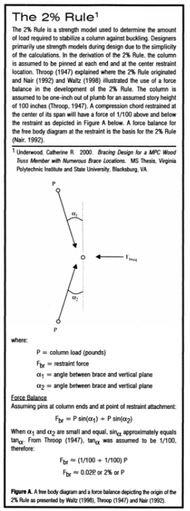
We've moved past this but, for interest's sake, the blurb below is one of the few places where I've found justification for the 2%. My records show that I picked this up from SRE and that the author was somebody by the name of Underwood.

c01_cen4rk.png
 
Aren't the alpha angles 1/50 if it's 1 inch out of plumb over 100 inches?
 
Status
Not open for further replies.

Part and Inventory Search

Sponsor