Eng-Tips is the largest engineering community on the Internet

Intelligent Work Forums for Engineering Professionals

Control Valve Authority Circuit Pressure Drop Calculation 1

Status
Not open for further replies.

IanVG

Mechanical
Jan 21, 2022
73
0
0
US
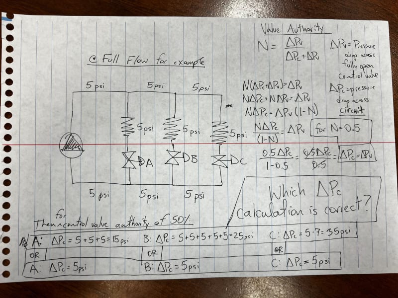
I'm sure this is very obvious to most, but for some reason, I have struggled to understand this. For calculating valve authority N=ΔPv/(ΔPv+ΔPc) where ΔPv is the pressure drop across the control valve when fully open, and ΔPc is the pressure drop across the circuit, what part of the hydronic system is ΔPc? Is it from the point where the branch taps off from the main? I am attaching a picture of my question with a sketch included.

Control_Valve_Authority_wffjus.jpg


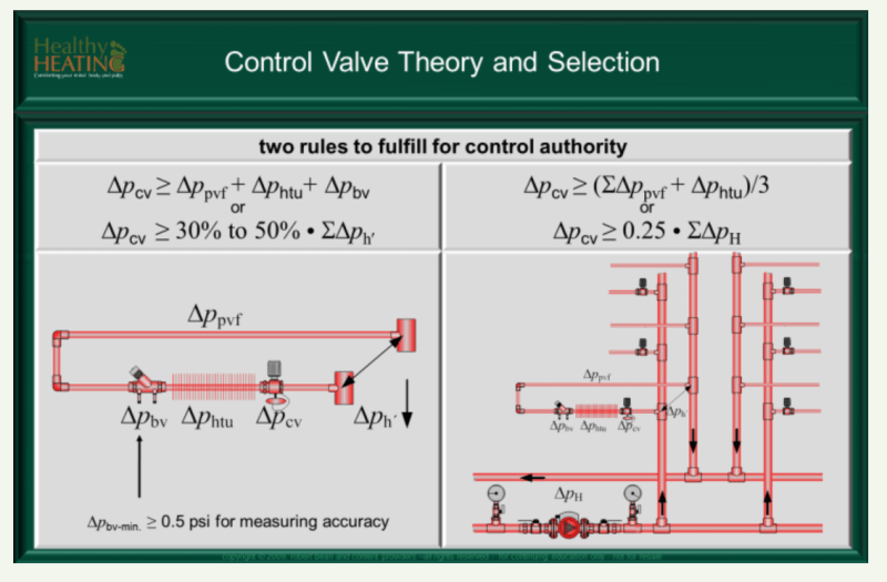
In addition, if I have a hydronic piping network with multiple branches that further split off to other branches, are there other 'rules of thumb' control valve authority values that are useful? I am attaching a picture from a slide on this issue. This slide suggests that ΔPc is the pressure drop from the inlet of the branch to the outlet (return).

Control_Valve_Authority_Parallel_u1xrbn.png
 
Replies continue below

Recommended for you

I'd say the branch circuit since that will change based on valve position. The overall system isn't very much influenced by that one valve. Like if you have a 100gpm system and that branch is only 2 gpm, that won't really impact the system.

In addition, if the system is very large and has large pressure drop, this shouldn't really impact valve selection.

I hope this is just a school exercise and not an actual new design. In 2023 everyone should use PICV and not worry about valve authority anymore. Just select the fwo rate and done.
 
HVAC-Novice thanks again for your insight. Unfortunately, it’s not! I’m modeling my campus hydraulically and part of what I’m doing is creating a model where I estimate valve Cv values and seeing how close to reality I match up. I suspect rules of thumb were used, so this is not too important but I want to understand 100% what I am assuming and why the assumption is valid.

In addition, I need to understand how DP control valves work in order to model the PICV’s in my particular hydraulic modeling software (I think).
 
PICV typically have 5 psi design pressure drop when open. You can hit up your local Belimo rep for advice. i use the 5pis or whatever the spec sheet says.

In the old days i used Honeywell valves. but their PICV had 3psi, 6 psi and so on. Belimo is easier since it is all 5 psi. It actually may be a bit different now with the ePICV (with flowmeter built in).

But I assume you are concerned with existing valves? So yo have to dig up what those are.
 
HVAC-Novice: gotcha. I’ve selected a few PICV’s and the process is much less painful. And right you are about having to find data on the existing control valves. I’ve found that most drawings do not include any Cv valves, so the process is nightmarishly difficult (think roughly 5000 control valves with no data). So before I collect data on all the control valves I’ll need to estimate to some level of confidence the performance of said control valves.
 
Your situation may be different. But older projects i saw, or newer projects from designers that never updated their thinking, left the final valve selection to the controls contractor. So if there are controls submittals, that may be where you can find them. that is, if the controls contractor was the one to provide the valves.

Many specs i saw mentioned to select valves for 5psi. But that doesn't mean that actually is what was used.

Many years ago I had built a schedule in Revit that would use the actual design flowrate and the valve I selected (with the Cv value) and then be calculated the pressuredrop for me so i can have it all calculated and scheduled. So I could select different valves till i found a satisfactory pressuredrop. Well, it was a lot of work and I figured I never use those valves anyway and just use PICV. Life is already hard enough, no need to make it harder:)
 
Status
Not open for further replies.
Back
Top