Eng-Tips is the largest engineering community on the Internet

Intelligent Work Forums for Engineering Professionals

  • Congratulations waross on being selected by the Tek-Tips community for having the most helpful posts in the forums last week. Way to Go!

Conversion of an induction motor into a synchronous generator 1

Status
Not open for further replies.

Sparweb

Aerospace
May 21, 2003
5,104
0
36
CA
This is about a generator being built for a wind turbine.
I have posted about this on Eng-Tips in the past, and while the discussions were fun, they did not elicit deep technical discussions or give me much additional knowledge about my project. I am looking for technical advice, reference materials, analytical depth. I have been doing this so far on rules-of-thumb and computer models I don't really understand. All I really want is a decent book that describes the electromechanical principles in enough mathematical detail that I can write my own modeling software.

My question:
How does one optimize a synchronous generator, either as a new construction, or when converting it from an induction motor through the addition of permanent magnets on the rotor?

The stock motor is a 3 HP Baldor. Here is the dataplate:
_Dataplate_jnybo7.jpg


20200303_175645_f6ahzr.jpg


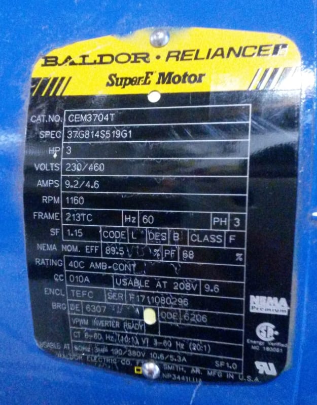
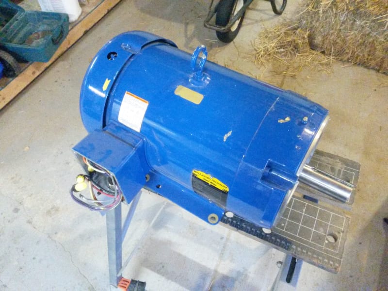
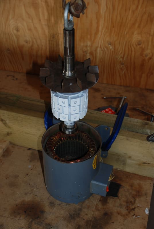
The motor is 6-pole, 3-phase, with dual voltage Star windings. I'll probably use it in Parallel-star. To convert into a generator, I only need to re-machine the rotor and put magnets on it. I have done it that way before, but I would like to do better this time. Here is what that looked like.

Baldor_Assy_DSC_1762_m1isxi.jpg


I am comparing two models that I have created in FEMM (Finite Element Magnetic Modeling). I am using this for lack of any other analytical tools to use that I know of - despite looking many times in many places. Book recommendations are still welcome!

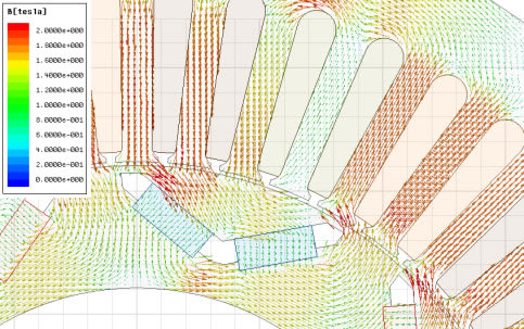
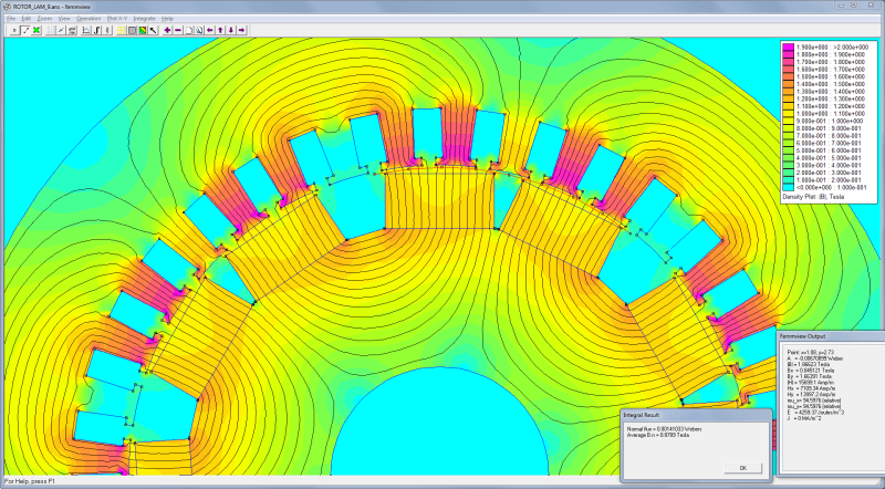
The image below represents a model of the machine I have already built in the past - with some modifications based on a machine I am preparing to build soon.

ROTOR_LAM_9_Capture_ffprdp.png


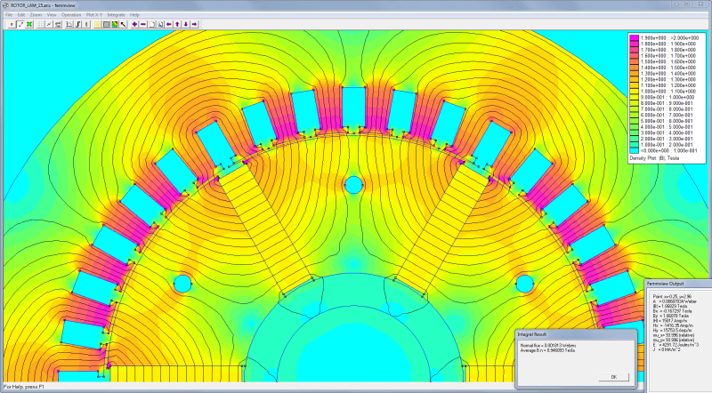
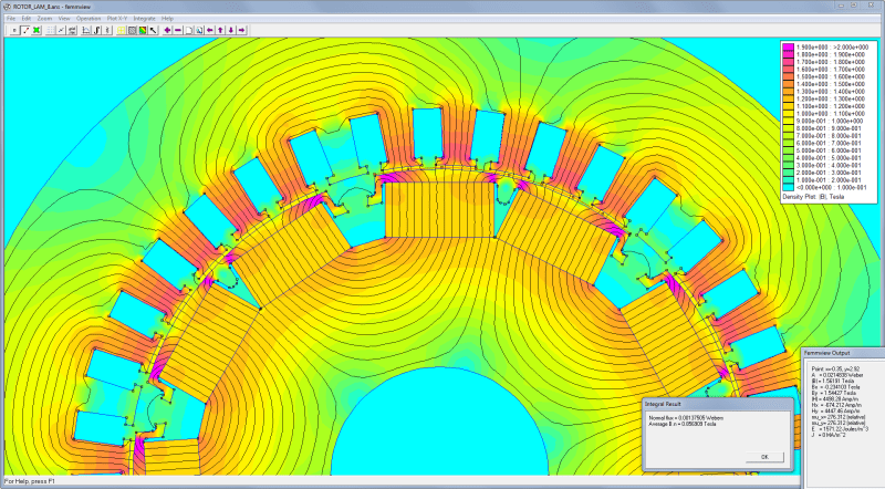
I was previously told that I could improve the machine by using pole shoes or some other means to reduce the air gap. So I've modeled that, too:

ROTOR_LAM_8_Capture_aqxigp.png


It's probably hard to read. The legend is scaled from 0.0 to 2.0 Teslas. There are areas with peak flux about 1.9T. Another thing that is hard to see in the graphic is that a line has been drawn between one of the poles and the stator teeth, across which FEMM measures the gap flux.

Without pole shoes: mean air gap 0.060 inch, Flux=0.00141 Webers
With pole shoes: mean air gap 0.0385 inch, Flux=0.00138 Webers

So I'm confused now. The mean air gap without pole shoes is almost twice as large as with them. The flux should be much smaller. The same magnets and all other components are identical in the two models.

But it's just a computer model, and I don't deeply know how it works, so is this "GIGO"?

If I were to set aside FEMM for a better way to design this, what would that way be?
What analytical tools exist to help me solve this for myself?
Is there a "back of the envelope" calc?

 
Replies continue below

Recommended for you

Hi
It seems that you have very thick magnets compared to mechanical air gap. Magnetic air gap (which defines the flux) is the thickness of magnet plus mechanical air gap length (because mpermeability of magnets is almost the same than with air). Between those two cases, I assume that the magnetic air gap changes only very little (since it is mostly defined by magent thickness, which is constant) and therefore you don't see any big change in flux.

With pole-shoes, you will have also bigger pole-to-pole leakage flux (this can be seen in you flux-plots), which would explain the fact the the total flux is even smaller despite the smaller air gap.

As a side comment, if those pole-shoes are massive steel (not laminated), you might want to check you how much you will have eddy current losses generated on those due to slot harmonics. They can be surprisingly big, depending on the frequency

Have you considered using curved magnets instead (without pole-shoes)? This way you can also minimize the air gap length without using pole-shoes.
 
General observations.
You magnet fill ratio is low. It might make sense for each pole to be made up of multiple smaller magnets to allow you to get more material into the rotor.
I can't really make a comment about the magnet size since we don't know the material.
But since no permanent magnet material has much real usable tensile strength, and they are all brittle I would not rotate this without some form of containment. A FRP overwrap would be the easiest.

= = = = = = = = = = = = = = = = = = = =
P.E. Metallurgy
 
I'm not trying to crap on your plans, but converted induction motors are considered about average as wind power alternators. They cog on start up which hurts the starting wind speed and the winding are too high a resistance which hurts higher wind speed efficiency. Have you considered building your own alternator completely from scratch? Personally, I would build a pancake style alternator like what otherpower.com has documented many times. I recall reading something over at otherpower about a scratch built alternator being capable of producing double the output compared to an induction motor when using the same blades.
 
Thank you for all the great comments.
I should have included the context at the beginning. The wind turbines are a project done in spare time for learning and fun, not for economic gain. That doesn't meant that there aren't people who express serious interest in buying one from me, but they are always shocked to hear how much it costs to make one. Even when doing the following things:
(a) Starting with a stock 3-phase motor and converting it, rather than making from scratch
(b) Not buying a PM generator which would cost drastically more and hard to find on e-bay too
(c) Perfectly functional stock 3-phase motors can be obtained from motor re-wind shops as discards for free
And those are just the "cheap out" steps for the generator. The blades and mountings are another story altogether.

But I have considered doing generators the other ways.
I have already built and burned out some of the "Otherpower" axial flux alternators. They can be made fairly robust but there are many weak points. I prefer to start with a machine that's already more robust than that.
The resistance in the windings of a 3-phase motor is definitely too high. On the face of it, re-winding with wire 3 or 4 gauges thicker will also reduce the turns count, and that would raise the cut-in speed. My current results already have a cut-in speed just about right. I would like to do a re-wind but it would probably take a lot of time to complete and I have no way to estimate the gains or aim for a target. Hence the request that I keep repeating with no answer "What book?"
This motor will likely have some cogging when converted, but there are ways to reduce it. The techniques I've already used are already sufficient. You can see the alternating pattern of magnets in the photo of the previous rotor above.
Curved magnets cost many times more than rectangular magnets. They are a special order, usually. You can sometimes find surplus arc segments, but the radius of curvature doesn't often fit. If you know of a source of arc-segment magnets that sells in quantities <1000 USD please let me know. Before the rare-earth price war, I once asked KJ Magnetic to quote and the minimum buy was about 5000USD in today's dollars and Neo prices.
The magnets in my model are certainly quite thick. I will pack on as much as I can fit, and as you've noticed there might be room for more. I am choosing from off-the-shelf sizes. My (probably flawed) thinking is that they need to be thick to counteract the flux from the armature.
The pole shoes will probably be vulnerable to eddy-current losses if I make them from a solid piece. Another obstacle to pole-shoes alongside the flux leakage.
Am I correct in believing that eddy-current heating is lower in sintered Neo blocks than it would be in a solid steel plate?
Which brings me to this enticing point:

jpts said:
It seems that you have very thick magnets compared to mechanical air gap. Magnetic air gap (which defines the flux) is the thickness of magnet plus mechanical air gap length (because permeability of magnets is almost the same than with air). Between those two cases, I assume that the magnetic air gap changes only very little (since it is mostly defined by magnet thickness, which is constant) and therefore you don't see any big change in flux.

I'd like to know more about that. What do you mean by permeability of the magnets? How permeable is Neo compared to steel/iron?
When I look at my diagram I see a gap about 0.04 inches. Are you referring to a gap of 0.54 inches due to the 1/2" thick magnet?

jpts said:
you might want to check you how much you will have eddy current losses generated on those due to slot harmonics.

I'd love to, and I've tried to figure it out. Unfortunately, all of the books I've bought on electromachinery and motor design do not offer much insight into how to do that. They're all great books but they don't offer the mathematics or the physics to work this out!
How did you learn to compute that? I don't think this is a simple problem to solve, otherwise the university textbooks would cover it.


Permeability means how well the material conducts magnetic flux. Iron has very high permeability, meaning that it has very small "magnetic resistance". Permanent magnets have very low permeability (about the same than air), meaning that they conduct magnetic flux very poorly. This means that most of the magnetomotive-force from the magnets is consumed in creating the flux in the magnet itself, and physical air gap plays minor role

Magnetic air gap is the thickness of the magnet (0.5 inches) plus the physical air gap (0.06 inches) -->0.56 inches with your design without poles shoes. With the pole-shoe design, it becomes 0.54 inches. So you can see, that even though you have reduced the physical air gap length by one third, magnetic air gap changes only by about 4%. This is the theoretical change in air gap flux. But due to higher leakage, the actual flux is even lower with pole-shoe design

Regarding eddy-currents, the only way to calculate them anywhere near accurately is to use FEM software (I'm not sure is FEMM capable of that, I'm using commercial software myself).

You can significantly reduce the eddy-currents on pole-shoes my making them from short segments (basically rings) in axial direction (e.g. ~ 0.5 inch axial length)
 
That changes my perspective drastically.

Sad to hear about the eddies. Pretty sure FEMM can't do it. AN$Y$ surely can.

Speaking of ANSYS, here's a pic from their website. This looks like a more efficient use of magnets:

ANSYS_ipm_map3_lq4zxv.jpg


There are motor winding manuals available, so a modest increase in wire size should be fairly straightforward. Rewinding inst that difficult. Though you could talk the motor shop where you pickup used motors as see what they would charge for the job.
Thinner magnets would help.
The inward angle does help reduce leakage, but can cause some other issues.
There are other magnet/pole shape options depending on how much machining you want to do.
I had a customer once that wanted to use one size of magnet on various rotors. The magnets were thin narrow rectangles (0.125"M x 0.250" x 1"). For each pole on small rotors he used 2 side-by-side, on large rotors (or lower pole counts) he used 3 magnets with the middle one up on a slight step. That way he could keep the pole shoes thin and mimic a curved magnet. And yes gluing down magnets next to each other of the same polarity is a PIA.

= = = = = = = = = = = = = = = = = = = =
P.E. Metallurgy
 
I actually have a copy of Rosenberg's book. It could be a straighforward process, but I find it very labour-intensive, even if one does have the bobbins. I have done some coil-winding myself already (axial-flux alternator projects in the past) and I found it took a lot longer than it seemed.

On the pro-rewinding argument, I have looked at the stator of the motor in question again, and I can tell the slot fill is rather low than I've seen on the other Baldors I have cracked open. Given that this is a "Super-E" and the others were "Premium" I was rather expecting to see tidy coils.

Just taking a guess from the image I stole posted above, it looks like the leakage flux between poles would re-direct to the stator tooth, depending on the tooth position and the amount of air gap. I plan to investigate with my (admittedly limited) tools.

 
A little bit more work made things come clear.
The magnets are driving the magnetic circuit, but they can be anywhere in the circuit. I didn't realize that you can literally think this way, much like the electric circuit must be complete for a current to flow. The coin dropped and I found a way to orient the magnet to make a strong field. The parts are easy to fabricate as flat laminations, and it needs a lot less magnet. Simple magnet shapes, too.

ROTOR_LAM_15_Capture_ntoxmu.png


Status
Not open for further replies.
Back
Top