This is about a generator being built for a wind turbine.
I have posted about this on Eng-Tips in the past, and while the discussions were fun, they did not elicit deep technical discussions or give me much additional knowledge about my project. I am looking for technical advice, reference materials, analytical depth. I have been doing this so far on rules-of-thumb and computer models I don't really understand. All I really want is a decent book that describes the electromechanical principles in enough mathematical detail that I can write my own modeling software.
My question:
How does one optimize a synchronous generator, either as a new construction, or when converting it from an induction motor through the addition of permanent magnets on the rotor?
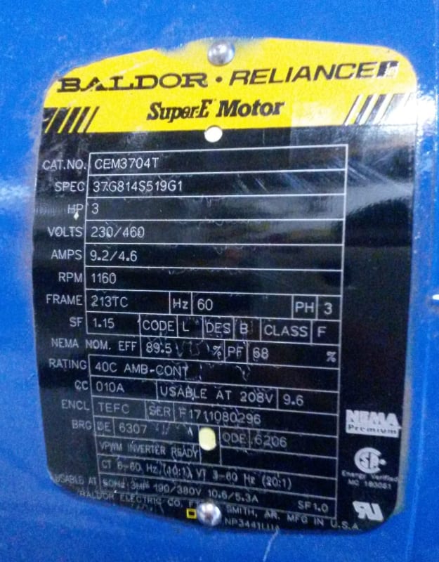
The stock motor is a 3 HP Baldor. Here is the dataplate:
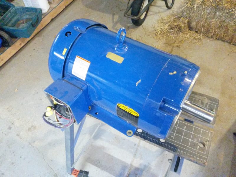
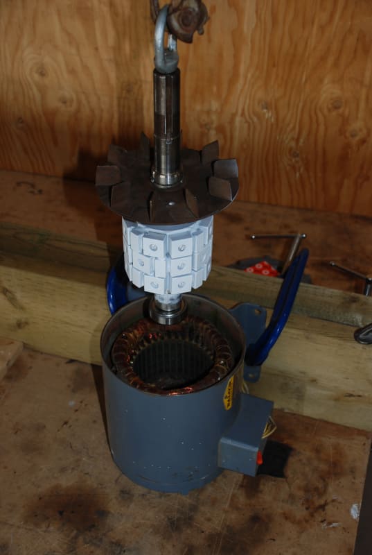
The motor is 6-pole, 3-phase, with dual voltage Star windings. I'll probably use it in Parallel-star. To convert into a generator, I only need to re-machine the rotor and put magnets on it. I have done it that way before, but I would like to do better this time. Here is what that looked like.
I am comparing two models that I have created in FEMM (Finite Element Magnetic Modeling). I am using this for lack of any other analytical tools to use that I know of - despite looking many times in many places. Book recommendations are still welcome!
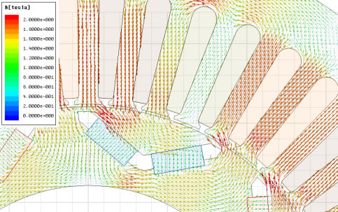
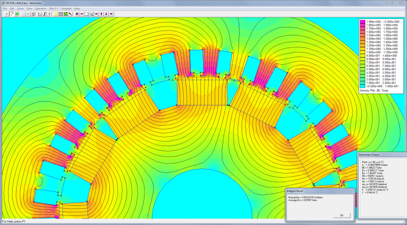
The image below represents a model of the machine I have already built in the past - with some modifications based on a machine I am preparing to build soon.
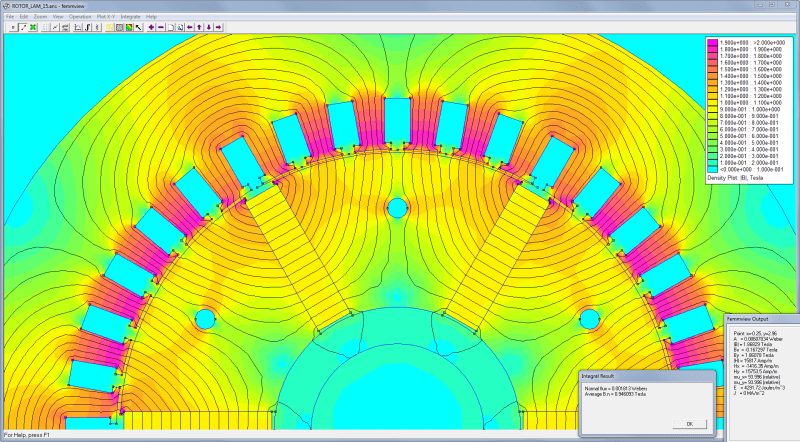
I was previously told that I could improve the machine by using pole shoes or some other means to reduce the air gap. So I've modeled that, too:
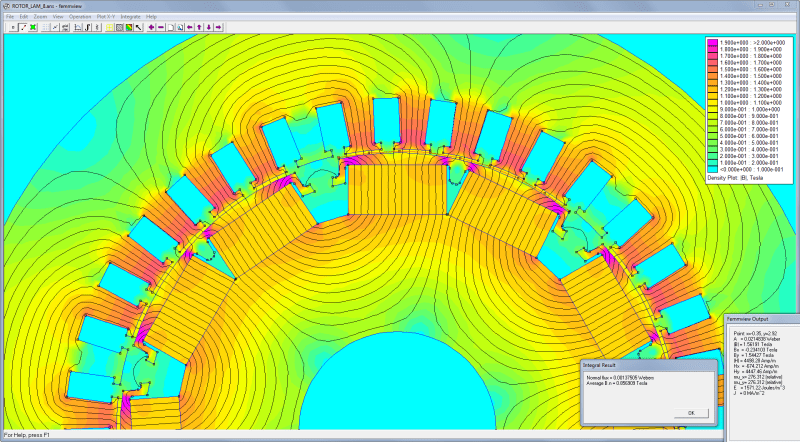
It's probably hard to read. The legend is scaled from 0.0 to 2.0 Teslas. There are areas with peak flux about 1.9T. Another thing that is hard to see in the graphic is that a line has been drawn between one of the poles and the stator teeth, across which FEMM measures the gap flux.
Without pole shoes: mean air gap 0.060 inch, Flux=0.00141 Webers
With pole shoes: mean air gap 0.0385 inch, Flux=0.00138 Webers
So I'm confused now. The mean air gap without pole shoes is almost twice as large as with them. The flux should be much smaller. The same magnets and all other components are identical in the two models.
But it's just a computer model, and I don't deeply know how it works, so is this "GIGO"?
If I were to set aside FEMM for a better way to design this, what would that way be?
What analytical tools exist to help me solve this for myself?
Is there a "back of the envelope" calc?
I have posted about this on Eng-Tips in the past, and while the discussions were fun, they did not elicit deep technical discussions or give me much additional knowledge about my project. I am looking for technical advice, reference materials, analytical depth. I have been doing this so far on rules-of-thumb and computer models I don't really understand. All I really want is a decent book that describes the electromechanical principles in enough mathematical detail that I can write my own modeling software.
My question:
How does one optimize a synchronous generator, either as a new construction, or when converting it from an induction motor through the addition of permanent magnets on the rotor?
The stock motor is a 3 HP Baldor. Here is the dataplate:


The motor is 6-pole, 3-phase, with dual voltage Star windings. I'll probably use it in Parallel-star. To convert into a generator, I only need to re-machine the rotor and put magnets on it. I have done it that way before, but I would like to do better this time. Here is what that looked like.

I am comparing two models that I have created in FEMM (Finite Element Magnetic Modeling). I am using this for lack of any other analytical tools to use that I know of - despite looking many times in many places. Book recommendations are still welcome!
The image below represents a model of the machine I have already built in the past - with some modifications based on a machine I am preparing to build soon.

I was previously told that I could improve the machine by using pole shoes or some other means to reduce the air gap. So I've modeled that, too:

It's probably hard to read. The legend is scaled from 0.0 to 2.0 Teslas. There are areas with peak flux about 1.9T. Another thing that is hard to see in the graphic is that a line has been drawn between one of the poles and the stator teeth, across which FEMM measures the gap flux.
Without pole shoes: mean air gap 0.060 inch, Flux=0.00141 Webers
With pole shoes: mean air gap 0.0385 inch, Flux=0.00138 Webers
So I'm confused now. The mean air gap without pole shoes is almost twice as large as with them. The flux should be much smaller. The same magnets and all other components are identical in the two models.
But it's just a computer model, and I don't deeply know how it works, so is this "GIGO"?
If I were to set aside FEMM for a better way to design this, what would that way be?
What analytical tools exist to help me solve this for myself?
Is there a "back of the envelope" calc?

