Continue to Site

Eng-Tips is the largest engineering community on the Internet

Intelligent Work Forums for Engineering Professionals

  • Congratulations GregLocock on being selected by the Eng-Tips community for having the most helpful posts in the forums last week. Way to Go!

Cooling of photodiode by thermoelectric cooling 1

Status
Not open for further replies.

tintin511

Nuclear
Feb 17, 2015
2
I have to cool a photodiode by a thermoelectric peltier module.
The circuit containing the diode look like this.
IMG_3997.jpg


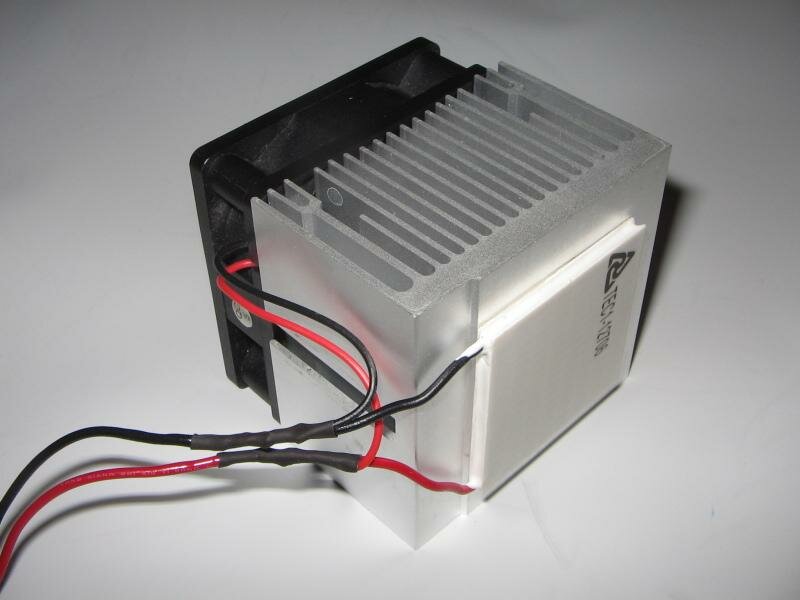
and the thermoelectric cooler with heatsink look like this.
with_heat_sink_thermoelectric_cooler.html


The cold side of the TEC module is giving -2 degree temp.
The problem is i have to put the Photodiode with circuit board within vacuum.

what is the best way to cool(direct or indirect cooling) the photodiode by the TEC module ?
 
Replies continue below

Recommended for you

The thermoelectric cooler with heatsink look similar like this
Peltier%20Cooler.JPG
 
"The problem is i have to put the Photodiode with circuit board within vacuum."

Do you? What temperature are you trying to achieve?

Why such a gigantic TEC? A photodiode has very little power dissipation, so you're mostly trying to cool convective heating from the environment itself. A smaller TEC would allow direct mounting of the TEC and the photodiode within a vacuum package.

TTFN
faq731-376
7ofakss

Need help writing a question or understanding a reply? forum1529

Of course I can. I can do anything. I can do absolutely anything. I'm an expert!
 
No, only the photodiode needs to be in the vacuum.
surface mount it to the TEC using the correct TIM (thermal interface material), and then run the leads out through a suitable pass-through to keep things sealed.

= = = = = = = = = = = = = = = = = = = =
P.E. Metallurgy, Plymouth Tube
 
I'd design the thermoelectric chip to be in whatever vacuum there is also - otherwise, expect it to fail in about 300-1000 hours, due to moisture intrusion (the cold face acts as a moisture trap, freezing out incoming water vapor that permeates through the seal. That trap keeps the vapor gradient to the outside, humid world at a maximum).
 
Two other issues with an external TEC is that the heat load will be upwards of 10x the heat load of just the detector, and the package exterior window may get fogged from being below the dewpoint of the environment.

TTFN
faq731-376
7ofakss

Need help writing a question or understanding a reply? forum1529

Of course I can. I can do anything. I can do absolutely anything. I'm an expert!
 
Obviously the hot side of the TEC needs to outside the chamber and the cold side inside the chamber.
Perhaps you could cut a window in your vacuum chamber and pot-in a block of copper or aluminium to give you a cold spot in the chamber. Square section to suit the peltier sounds nice but round would probably be easier to make, fit and seal. Make the block with a shoulder to rest on the outside of the chamber wall.
You haven't said whether you are dealing with high vacuum here, if so you have a whole different ball game in terms of materials, sealing etc.
If the entire cct bboard is in the chamber any other heat generated can only conduct to either the cold Photodiode or radiate to the walls of the vacuum chamber (if the delta T is favorable.) So it may be worth cooling the whole board direct to the cold spot.


je suis charlie
 
Actually, most purpose-built TEC-cooled circuits have the entire TEC inside the vacuum space, with the hot side bonded to the package bottom.

TTFN
faq731-376
7ofakss

Need help writing a question or understanding a reply? forum1529

Of course I can. I can do anything. I can do absolutely anything. I'm an expert!
 
"package bottom"?
Is that the vac chamber wall?

je suis charlie
 
If you look at the photo posted by the OP, the round can in the upper right would be an example of a photodiode package that could house a TEC under the detector. With the use of reflective surfaces internally to reduce thermal emission, the heat load on such a TEC would be miniscule, so something like: would work

If the TEC were outside of and under the package, the heat load would be significantly higher, since convective heating from the air would compete with the TEC. Moreover, if the TEC setpoint was below the dewpoint, the package and window would cause condensation, which could damage the TEC as well prevent efficient collection of a photo signal.

TTFN
faq731-376
7ofakss

Need help writing a question or understanding a reply? forum1529


Of course I can. I can do anything. I can do absolutely anything. I'm an expert!
There is a homework forum hosted by engineering.com:
 
The hot side of the TEC has to be outside the vacuum chamber.

je suis charlie
 
That's desirable, but not required. Almost all of our bolometer detectors used to have the TEC inside the vacuum package, as seen below

download.aspx


TTFN
faq731-376
7ofakss

Need help writing a question or understanding a reply? forum1529


Of course I can. I can do anything. I can do absolutely anything. I'm an expert!
There is a homework forum hosted by engineering.com:
 
So the hot side of the TEC mounts to the wall of the vacuum chmber and the heat conducts to the environment?

je suis charlie
 
Basically. You bolt the bottom of the case to a heat spreader; you can see two of the 4 cutouts for the bolts.

TTFN
faq731-376
7ofakss

Need help writing a question or understanding a reply? forum1529


Of course I can. I can do anything. I can do absolutely anything. I'm an expert!
There is a homework forum hosted by engineering.com:
 
my [case] = your [vacuum chamber]

TTFN
faq731-376
7ofakss

Need help writing a question or understanding a reply? forum1529


Of course I can. I can do anything. I can do absolutely anything. I'm an expert!
There is a homework forum hosted by engineering.com:
 
Status
Not open for further replies.

Part and Inventory Search

Sponsor