Eng-Tips is the largest engineering community on the Internet

Intelligent Work Forums for Engineering Professionals

Cooling Tank Sizing 5

Status
Not open for further replies.

Al_eng

Mechanical
Jul 22, 2020
6
0
0
GB
Hello I'm looking for advice on if I'm approaching this problem in the correct way whilst trying to keep it simple.

I'm designing a rectangular stainless steel cooling tank which will be located outside with no insulation.

I have 170kg/hr of water at 90°C entering a tank under gravity flow, I need the water leaving the tank to be less than 60°C (also under gravity flow).

I've made a guess on the dimensions of the tank to give a starting point to the calculations. Area of water in contact with the tank walls of 0.675m^2 and a wall thickness of 6mm
Outside mean average summer temperature 14°C

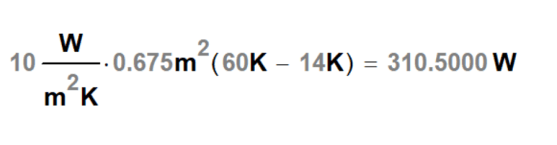
I've calculated the heat loss from the tanks walls:-

q = 15 W/mK x 0.675m^2 x [ (60°C - 14°C) / 0.006m ] = 77.6 kW

I've calculated the heat gain from the hot water entering:-

Q = 170kg/hr x 4190 J/Kg °C x (90°C - 60°C) = 5.9 kW

As the heat loss from the tank is more than the heat gain am I right in saying the temperature of water leaving the tank will be less than 60°C?

I know there's a lot of factors I haven't taken into consideration to try to keep it simple such as lower night temperatures, wind, heat from the sun (tank positioned in a shaded location)
I was also planning designing the tank with baffle plates to promote free mixing to help with the assumption that the contents of the tank will reach a temperature equilibrium.

Thanks in advance
 
Replies continue below

Recommended for you

Well that's a start, but you must include the time factor. Heat gain or loss is a flow of heat over time.

The temperature of a tank of water depends on the flow of heat, which increases temperature when you have a positive flow of heat into the tank and decreases when the net heat flow is out of the tank.

Since heat outflow from the water in the tank is greater than heat inflow into the tank, yes, the water will cool towards becoming equal to outside ambient temperature, but you do not yet know what temperature it will reach. That depends on the initial water temperature and how long you pump hot water in and how long the outside temperature remains at 14°. Both will affect the cooling rate, so that probably does not remain constant for very long. You do not know if the temperature of the tank will be lower than 60° before sunrise starts warming the air and changing that 14° ambient temperature. You must include the time that you assume those variables to be constant in order to determine the temperature of the water in the tank as it progresses through time.

--Einstein gave the same test to students every year. When asked why he would do something like that, "Because the answers had changed."
 
Hi 1503-44 thanks for the quick reply.

The 14°C is the average summer day time temperature (it's a cold part of the world [bigsmile] )
Yes I was trying to look at it as a moment in time to simplify the calculation.

The 170kg/hr is the worst case and is assumed to be 24/7.

It's calculating the temperature when mixing the incoming hot water with the tank contents which I'm unsure off and the reason why I stuck to heat gain < heat loss. If it was a set volume of each that would be easy but here I have a constantly moving fluid. Do you know of a resource that can point me in the direction of how to do this calculation?

As it's a new installation I could recommend the tank is first filled with cold water.
 
Allysuth,

You've not included the most important factor which is wind speed on the tank or fins.

Your calculation is flawed in that you only appear to be considering the heat transfer from inside the tank to outside the tank as though all that heat can be lost to the air. It can't.

Still air heat convective loss from a vertical plate is around 20-30 W/m2K. So assuming your surface area is the vertical section? then you're looking at approx 25 * 0.675 * (75-15) = ~ 1kW

So I think you will have water at about 85C exiting the tank.

You have quite a large volume with not much surface area - think of the elephant versus the mouse.
Actually what are the dimensions / volume of this tank?

But if you have 5m/sec wind then your HTC could increase by 3 to 5. Also add some fins / more square area and you might get there.
Or make the tank a lot longer and narrower to increase surface area by a factor of 5 to 6.
Or run it in a pipe.

Also you haven't allowed for Solar heating?

Remember - More details = better answers
Also: If you get a response it's polite to respond to it.
 
Allysuth said:
I need the water leaving the tank to be less than 60°C ...
q = 15 W/mK x 0.675m^2 x [ (60°C - 14°C) / 0.006m ] = 77.6 kW
Incorrect.
You assumed that wall water temp is equal to bulk water temp at cooler outlet.
Assuming that flow regime is laminar one of those temps in reality will be much much higher.
 
"Area of water in contact with the tank walls of 0.675m^2"
That is a rather small tank. It makes a big difference whether the water flow is from top to bottom or vice versa. You want flow to be from top to bottom. Then hotter water will stay at top and cool at an asymptopocally decreasing rate (approaching zero when water temp is equal to ambient) as it moves down. If the top of the tank is open, most of the cooling will occur there. You could spray the water into the tank and use evaporation. Then you have somewhat of a cooling tower.
 
A quick back calculation shows your volume is about 0.04 m3 or 40kg of water. So your residence time is about 15 minutes from water in to water out.

Remember - More details = better answers
Also: If you get a response it's polite to respond to it.
 
I need the water leaving the tank to be less than 60°C ...
q = 15 W/mK x 0.675m^2 x [ (60°C - 14°C) / 0.006m ] = 77.6 kW

Aside from the issues mentioned by others, your equation is for the thermal conduction of the wall, and not the convection from the wall; that's obvious from the inclusion of the wall thickness, which convection doesn't care about.

But, yes, the non-mixing of the tank contents means that there may be a huge amount of fluid that at a much higher temperature than desired. Using only the tank walls for heat transfer is not sufficient for proper cooling

TTFN (ta ta for now)
I can do absolutely anything. I'm an expert! faq731-376 forum1529 Entire Forum list
 
I believe that your basic method of assuming if the heat transfer from the walls is greater than the heat input into the vessel at 60C wall temperature then you should get approximately correct results. Assuming that your flow does not short circuit from the inlet to the outlet and spreads out evenly in the tank. At such small flows and inlet velocity it appears that short circuiting of flow from the inlet to outler will not be an issue.

However as others have mentioned but not clearly I believe, is that there are actually 3 heat transfer surfaces in series not one that you are using of the thickness of the plate, as the plate resistance to heat transfer is negligible. The three heat transfer sufaces are as follows:

Inside wall convection coefficient hi

Tank wall metal conduction coefficient k

Tank outside air film coefficient ho

k of the wall can be neglected likely since it is negligible compared to the other two

ho of the outside film is likely the largest and governing. For still air on a vertical surface ho = 1.47 BTU/hr/ sq ft-degF or the resistance R to heat flow is 1/U = 1/1.47 = 0.68.

Since overall U value is sum of 1/R where R is the resistance of each layer to heat transfer then total U is

U = 1/SUM(R) = 1/(1/hi + dx/k + 1/ho)

Without considering the other two resistances the outside film resistance of 1/1.47 = 0.68 will give an overall heat transfer coefficient of 1/0.68 = 1.47. I don't know what the inside film resistance of still water film on a vertical plate but there may be some information in heat transfer books, but I think it will also be significantly lower than the outside air film coefficient but maybe not negligible.

I believe the correct conversion of k = 15 w/m-K is 8 BTU/hr-ft-F. and with dx = .006 meters then dx = 0.0197 feet and then R = (dx/k) = 2.46E-3 for the plate. Plugging into the equation for U above and not considering the internal convection resistance hi:

U = 1/SUM R = 1/(1/1.47 + 2.46E-3) = 1/.6827 = 1.4647

(Where Q = UAdT)

So the change in overall U by including the resistance of the plate to resistance of outside film is negligible.

Note also that in your OP calculation you should have multipled the heat transfer calculated by 4 if you have 4 walls all equal in area.

Also there is heat loss from the surface of the liquid, assuming an open tank, by convection and through evaporation loss which if neglected would just give you more conservative results.
 
Thank you all for taking the time to reply.

I have estimated the tank dimensions as a starting point, starting small (600mm x 300mm x 400 high)
The area 0.675m^2 was for the 4 sides and the base only.

Hopefully this link works for the concept sketch:-

I will take onboard the comments and carry out a more in-depth calculation
 
Allysuth said:
carry out a more in-depth calculation
The task seems is more relevant to CFD modelling rather than manual calculation. CFD is not so tricky and time consuming is it may seem.
Note that combination of negligible details like surface emmisivity, form, shape, porosity, sludge/debris built-up have major impact on heat flux resulted.

You have the small scale self-driven self-controlled non-intensified environment on both sides - air and water. For cases such kind of final credibility of a report weather calculated by handbooks or modelled by a software is a big question.
 
Looks interesting.

Just think that what you have there is essentially a domestic radiator. Think how little heat you would get out of one that small... With no fins and no wind. 1kW might be generous.

Remember - More details = better answers
Also: If you get a response it's polite to respond to it.
 
Not a homework question, as it's been 10+ years since I was last a student.

90°C is the conservatively estimated temperature of the waste condensate from an industrial steam process, it is not suitable for recovery and therefore requires to be cooled prior to being discharged to drain. 43°C is the typical allowable temperature for public sewers but as it's for a private industrial site (not connected to the public sewers) less than 60°C is the target temperature to ensure the drain material integrity remains. Currently the condensate is cooled by mixing with fresh water which is incredibly wasteful so I'm trying to design a more sustainable alternative not using water whilst taking advantage of the cooler climate to do the hard work.
 
You need to increase the surface area exposed to air either with fins, using pipe or just using a vehicle radiator with an electric fan

Or a cooling tower.

Anything is better than a tank.

Remember - More details = better answers
Also: If you get a response it's polite to respond to it.
 
Fortunately, you're "only" trying to push 5.9 kW of heat out

Unfortunately, you need at on the order of 19 of these boxes to do the job, even when assuming 46C deltaT across every single thermal interface to the air on every single box. THAT is not going to happen, so you need to come up with a different cooling scheme, like maybe the cooling tower mentioned above. The bottom line is that you need somewhere between 20x to 30x increase in your heat transfer equation to get your heat flow out; that means a combination of improved heat transfer coefficient, as in forced convection, or massively more cooling area.

Below is my calculation of what your box might be able to do; it ignores anything going on inside the box, so that's where the upper bound is uncertain.

heat_q1jl7r.png


TTFN (ta ta for now)
I can do absolutely anything. I'm an expert! faq731-376 forum1529 Entire Forum list
 
A 3/8inch plain SS tubing may give you about 15w/m2/degK (rough indication - see table 5-2 for natural convection + radiation htc in Perry Chem Engg Handbook, 7th edn) based on external surface area, so that amounts to approx 4.7 x 15 x (75-25) = 3500w per 100m of linear length. For 5900w, that requires about 170m of total length. If you split this flow into 3 bits of 3/8inch tubing hooked up in parallel, total length for each = 55m. Flow is laminar so resistance hi will probably dampen this a bit, but this gives you a rough idea.

Finned tubing will perform better. Fin thermal eff can be taken as 0.5 for starters. Speak to finned tube suppliers - choose extruded SS fins for reliability.

 
In a little while we would move to draft finned air coolers and after which we will find out that this is a common cheap device spread all around the world regions and industries that is more practical to be specified the R&D of a new one.
What is the reason to reinvent the wheel?
 
Innovation?
Sustainability? trying to not use cooling water or electricity (which isn't readily available in location either)
Restricted size due to location
Restriction due height of inlet pipe
It's not a massive amount of water that's being considered

If the size of tank required to allow the cooling works out to be 20m x 20m x 20m then obviously that wouldn't be practical but at the moment that's the unknown which if why I was asking for advice
 
Status
Not open for further replies.
Back
Top