Continue to Site

Eng-Tips is the largest engineering community on the Internet

Intelligent Work Forums for Engineering Professionals

  • Congratulations pierreick on being selected by the Eng-Tips community for having the most helpful posts in the forums last week. Way to Go!

Cooling Tower Spray Pipe Pressure Drop Calculation 5

Status
Not open for further replies.

Pavan Kumar

Chemical
Aug 27, 2019
376
Hi All,

I am trying to calculate the pressure drop across the Spray Pipe system for our Cooling Tower cell. We have two cells namely the South and the North Cell. The intention is to rate the existing Cooling Tower circulation Pump for higher flow rate. The pump is supposed to flow 4176 US gpm. I have arbitrarily assumed that the South Cell is getting 2000 gpm while the North gets 2176 gpm. I will get the correct flow rate after I finish my total pressure drop calculations.

CT3_egbfak.jpg


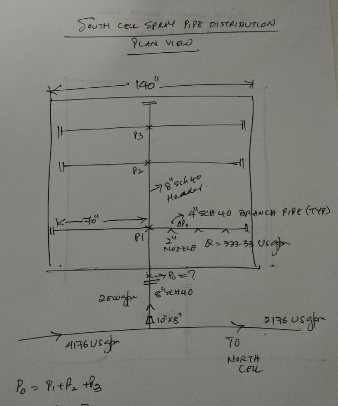
Each of the cell has Spray Pipe distribution that sprays hot return cooling water at 32 Deg C on the fill. In-order to size/rate the pump I need to calculate the pressure drop in each of the cell. The pressure drop in each cell is the total of the pressure drops in each of the spray pipe branches.

The calculation spreadsheet based on Perry's 9th Edn Section 6-31 is attached with this thread.
I have calculated the pressure drop in the spray hole= DPo = 4.2 psi

Assuming the spray pipe branches get equal flow, the flow rate in each SPray pipe brnach = 2000 / 6 = 333.33 gpm

Using the flow rate, I calculated the pressure drop across each hole as DPo= 4.2 psi.

There are 3 holes in each spray pipe branch. The total pressure drop of all the holes = 4.2*3 = 12.6 psi.

Per Perry Section 6-31, the pressure variation over the length of the perforated pipe = 1/10th of the pressure drop in the holes

So the pressure drop in the spray pipe branch = (1/10)*4.2*3 = 1.26 psi.

Since two branch start at the same point on the header. The pressure at the center junction point is saame.

so P1 = 1.26 psig, P2 = 1.26 psig, P3= 1.26 psig.

The total pressure at the cell inlet, Po = P1+P2+P3 = 1.26*3 = 3.78 psig.

So each pressure drop P1 = 1/10(4.2*3)=1.26 psi

So the total pressure P0 =(1.26+1.26+1.26)=3.78 psi.

I want to make sure that is analysis is correct.

Thanks and Regards,
Pavan Kumar


Replies continue below

Recommended for you

Your approach is completely wrong. The flows through the holes in a single branch are in parallel and not in series so you cannot add the pressure drops through the holes to say that "The total pressure drop of all the holes = 4.2*3 = 12.6 psi." You need to revise the concepts of pressure and pressure drop to ensure you understand the difference between these concepts.

The usual way to analize a network like this is to assume that the flow rate through each of the holes (or more usually nozzles) is the same. For each hole to deliver the same flow rate it is necessary that the pressure inside the branch pipes is the same at every hole position. It is for this reason that Perry specifies that the pressure drop through the header and branch pipes should be less than 10% of the pressure drop through the hole. But this is a target and not a method of calculating the pressure drop through the branch. The actual pressure drop along the branch should be calculated using the usual methods such as the Darcy-Weisbach or Hazen-Williams equations.

Experience has shown that if the pressure drop along each of the branches and header sections is less than 10% of the pressure drop through the hole then the assumption that the flows through each of the holes is the same is valid.

So first you calculate the pressure drop through the hole - your 4.2 psi for this seems reasonable. The next step is to calculate the pressure drops through the header and branches to check that they are indeed less than 10% of the pressure drop through the holes. This enables you to calculate the external piping and the pump by taking the flow into Po as 2000 USGPM with a residual head of 1.1 x 4.2 = 4.6 psi.

If you are re-rating the cooling towers then you would have to recalculate the pressure drop through a hole at the new flow rate and then check that the calculated pressure drop through the internal header and branches is still less than 10% of the pressure drop through the hole.

Katmar Software - AioFlo Pipe Hydraulics

"An undefined problem has an infinite number of solutions"
 
Hi Harvey,

Thank you very much for reviewing my calculations and correcting me. I got confused by the example given in Perry section 6-31. I worked my problem below as per this section.

-------------------------------------------------------------------------------------------------------
Method-1:

Per this section the pressure drop in the perforated pipe is given by

DP = ( 4fl/3D -2K)*(Rho*Vi^2)/(2*gc) <---- Eqn 6-156 , Section 6-31.

where
K = 0.5 for discharge manifolds.
L,D and Vi are the length, Diameter and Velocity in the perforated pipe in feet.
f is the fanning friction factor in the pipe and Rho is the fluid density in lb/ft3.

Also it says for 5% maldistribution, the pressure drop per hole, DPo ~= 10 x DP.

Assuming the flow splits equally in each branch pipe, the flow rate in each branch pipe is 333.33 gpm (=2000/6)

Perforated Pipe Pressure Drop Calculation:

Flow rate = 333.33 gpm = 0.7426 ft3/sec
Line Size = 4" Sch 40
D = 4.026 inches = 0.3355 ft
Length, L = 5.833 ft
Pipe Area, Ap = 0.0884 ft2
Velocity, Vi = 0.7426/0.088 = 8.4 ft/sec
Rho = 62.0655 lb/ft3
NRe= 331156
f = 0.00526

DP = [(4*0.00526*5.833)/(3*0.3355)-2*0.5]*(62.0655*8.4^2)/(2*32.174)
= 59.76 lbf/ft2 = 0.415 psi.

So hole pressure drop DPo= 10*DP =10*0.415 = 4.15 psi

Hole Pressure drop for a perforated pipe is given by DPo= (1/(Co^2))*(Rho*Vo^2)/(2*gc) <-- Eqn 6-158

where Co is the orifice coefficient = 0.62
Vo is the hole velcocity

Back calculating the hole velocity from the above formula, Vo = 15.4 ft/sec.

Since for 5% maldistribution, DPo=10*DP

Vo/Vi = Ap/Ao

where,

Ap is the pipe area
Ao is rhe total hole area

Ao = 0.0884/ [(15.4/8.4)] = 0.0482 ft2 = 6.94 inch2

Area per hole, ao = Ao/3 = 6.94/3 = 2.314 inch2

Hole Dia, do = SQRT(4*ao/PI) = 1.716 inch

Actual hole is 2" inch.

Assuming the pressure drop in the header pipe is <10% of the hole pressure drop.

Total pressure drop in the distribution system = 1.1*DPo = 1.1*4.15 = 4.565 psi.

Po = 4.5765 psig.

-------------------------------------------------------------------------------------------------------

Method-2:
I re-calculated the pressure drop per hole, branch pipe, and header. I assumed that the flow is splitting equally through all the branches, even though In actuality it is not. I also assumed that the flow in hole (nozzle) is also same per 5% maldistribution criteria in Perry Section 6-31.

A) 8" header Pressure Drop Calculation

The flow in the 8" header section when it enters the cell is 2000 US gpm. The flow then splits to two branches with 333.33 gpm in each. The flow in the header section then falls to 1333.33 gpm (=2000-2*333.33). The flow again splits into two branches again each with 333.33 gpm. The flow in the header section is now 666.66 gpm(1333.33-2*333.33). The flow finally splits again into two branches again with 333.33 gpm each.

I calculated the pressure drop in the 8" header sections sequentially and added the pressure drops.

The flow rates and pressure drops in each section are as follows:

(i) 8" Header section between the cell inlet and the first branch ( with two branch pipes on either side of the header section)

Flow rate = 2000 gpm,
Line velocity = 12.83 ft/sec
Section Length = 3.5 ft
Pressure drop, DP1 = 0.43 psi

(ii) 8" Header section between first and second branch

Flow rate = 1333.33 gpm,
Line velocity = 8.55ft/sec
Section Length = 3.5 ft
Pressure drop, DP2 = 0.19 psi

(iii) 8" Header section between second and third branch

Flow rate = 666.66 gpm,
Line velocity = 4.28 ft/sec
Section Length = 3.5 ft
Pressure drop, DP3 = 0.05 psi

Total Pressure drop in 8" Header = DP1+DP2+DP3 = 0.43+0.19+0.05 = 0.67 psi

B) Hole Pressure Drop Calclation
The flow rate in each branch pipe is 333.33 gpm (=2000/6). The flow rate through 2" hole (nozzle) is also assumed to be split equally that is flow rate in each hole = 333.33 / 3 = 111.11 gpm ( for three holes)

Hole diameter, do = 2" = 0.167 ft
Number of holes(nozzles) per branch pipe = 3 ( as per the existing spray pipe distribution)
Flow rate per hole = 333.33/3 = 111.111 gpm = 0.2475 ft3/sec

Hole area, ao = (PI/4)*(do^2) = (22/7/4)*(0.167^2)= 0.0218 ft2.
Hole velocity, Vo = 0.2475/0.09218 = 11.3 ft/sec
Hole Pressure drop, DPo = [1/(Co^2)]*(Rho*(Vo^2)/(2*gc) <-- Eqn 6-158, Perry Section 6-31, 9th Edn
where Co = 0.62 <-- Orifice coefficient.

DPo = (1/(0.62^2))*62.0655*(11.3^2)/(2*32.174) = 323.07 lbf/ft2 = 2.24 psi

C) 4" Branch Pipe Pressure drop Calculation

Flow rate in the 4" branch pipe between the entrance and the first take-off(2" hole) is 333.33 gpm and after at the first take off point the flow rate reduces to 222.22 gpm (=333.33 -111.11). After the second take-of point the flow rate is 111.11 gpm(=222.22-111.11). Performed pressure drop calculations sequentially for each of the branch pipe sections as below:

(i) 4" Branch pipe section between entrance and first hole:
Line Size = 4" Sch 40
Flow rate = 333.33 gpm
Line length = 1.45 ft
Velocity = 8.4 ft/sec
Pressure drop, dp1=0.2178 psi

(ii) 4" Branch pipe section between first hole and second hole:
Line Size = 4" Sch 40
Flow rate = 222.22 gpm
Line length = 1.45 ft
Velocity =5.60 ft/sec
Pressure drop, dp2=0.03 psi

(iii) 4" Branch pipe section between second hole and third hole:
Line Size = 4" Sch 40
Flow rate = 111.11 gpm
Line length = 1.45 ft
Velocity =2.80 ft/sec
Pressure drop, dp3= 0.02 psi

4" Branch Pipe pressure drop = dp1+dp2+dp3 = 0.2178+0.03+0.02= 0.2678 psi.

Summary:
1. Hole Pressure Drop, DPo = 2.24 psi
2. 4" Branch Pipe pressure drop = 0.2678 psi = 12% of DPo
3. 8" Header Pipe Pressure drop = 0.67 psi = 30% of DPo

Total pressure drop in Spray pipe distribution system = 1.1*DPo = 1.1*2.24= 2.464 psi.

As you said, the branch and header pipe pressure drop needs to be less than 10% of the hole pressure drop. In this case the pressure drop in the branch is slightly higher while the header pressure drop is quite high. I want to check if the calculations I did are correct. If they are correct then does it mean the flow is not uniform or am I missing something here. Your comments will be very helpful.

Thanks and Regards,
Pavan Kumar
 
Hi,
To add to the discussion, you may find some analogy with the design of a sprinkler system.
Document attached
Note: you still have the possibility to download from Internet PSIM2 (process simulation improvement modeling tool) for free and perform your calculation. Together with the tool you have access to several examples for self-teaching.
Hope this is helping you and others.
Pierre
 
It will never be possible to achieve total uniformity of flow in the distribution piping but once you have determined what variation you can tolerate between the maximum and minimum flow through the holes then you can check if the flow through the distribution piping is sufficiently uniform. We know that the pressure drop through the holes is proportional to the square of the flow rate. So if we decide that we can tolerate a 5% flow variation between the max and min hole flows then the pressure variation will be 1.05^2 = 1.1025 and this is where the 10% rule of thumb for the piping pressure drop comes from.

This rule of thumb can be used in the reverse direction as well. If it turns out that the pressure drop through the piping is 15% of the hole pressure drop then you can estimate the variation in hole flows by taking the square root. The flow variation will be 1.15^0.5 = 1.072 and then you have to use your engineering judgement to decide if the 7.2% flow variation is acceptable.

The calculation of the pressure drop through the headers and branches can be quite complicated. As you have shown in your example C, the flow changes at each hole and at each intersection. In a simple and small distribution system it can be adequate just to assume that the flow is the same all along the pipe and base the pressure drop on that. In more complex systems you have to calculate it step by step as you have done. In some cases it is even possible to change the pipe diameter along the pipe. You will often see this in air conditioning systems where the ducts are large and savings can be made by using smaller piping where possible.

It can even be necessary to calculate the pressure recovery as the flow velocity in the pipe decreases after a hole or branch. For example in you Ci calculation the velocity is 8.4 ft/s. This makes the velocity head in the first section 0.46 psi. (BTW the friction pressure drop of 0.2178 psi for Ci is wrong.) In the second section (Cii) the velocity has decreased to 5.6 ft/s and the velocity head is 0.21 psi. The recovered pressure from the velocity head is 0.25 psi and this is more than the frictional pressure drop between the first and second holes (which is correctly calculated). So here you have the unexpected situation where the pressure in the branch pipe is greater at the second hole than at the first.

Katmar Software - AioFlo Pipe Hydraulics

"An undefined problem has an infinite number of solutions"
 
Hi pierreick,

Thanks a lot for sending the Sprinkler System Design document. It is an invaluable document and I shall work through it. As always you are resourceful with the correct documents that can and should refer to. I am grateful to your help all along.

This document might give the solution that I am looking for.

Thanks and Regards,
Pavan Kumar
 
Hi Harvey,

I did not fully understand the flow variation between min and max hole flows. I think we already have a variation with one flow that is 2000 gpm itself. This 2000 gpm is with considering the new flow rate of 4176 gpm for both the cooling tower cells for which the CW pump is being sized/rated for. The existing / current flow rate is 3500 US gpm. This is for pump sizing calculation only. We will later have to rate the Cooling Tower itself for the heat load of q = 50 MM Btu/hr from the current load of 41.5 MM Btu/hr to see if this existing CT will still work. Once this calculation is finalized I will post the calculation for CW pump sizing that I am almost done(pending the spray pipe DP calc).

In my problem, the pressure drop in the

(i) 4" branch header DP = 0.3647 psi(0.305+0.055+0.0046)= 16.3% of DPo.
(ii) 8" Header DP = 0.67 psi = 30% of DPo.

The pressure drop in the first section of the 4" branch pipe is totalled as below:

(i) Flow Thru Branch - 0.027 psi
(ii) 8"X4" Reducer -0.155psi(the 4" branch from the 8"header is modeled as Flow thru branch + 8"X4"red)
(iii) 1.45 ft of st pipe - 0.0368 psi
(iv) Flow thru Tee - 0.086 psi ( for the flow past the first hole)
----------------------------------------------------------------------------------------------
Total = 0.027+0.1550+0.0368+0.086 = 0.305 psi. ( Corrected from 0.2168 psi from yesterday.)
----------------------------------------------------------------------------------------------

If add up these two pressure drops the total=0.3647+0.67 is 1.0347 psi (46.2% of DPo)

As you are saying the hole flow variation is 1.462^0.5= 1.21 that is 21% variation in the flow. Is this analysis correct?. If yes I feel this is not acceptable, but have to live with it as this is existing installed system. We can accept up to 5% variation. Also we are not sure if the branch headers are getting the same flow. Non-uniform flow distribution will affect the Cooling Tower performance also. We assumed the same flow for simplicity. I will work through Sprinkler design doc sent by Mr. Pierre.

So in conclusion can say the pressure Po at the Cooling Tower Cell inlet is DP1(Branch)+ DPo(Hole)+DP2(8"Header) = 0.3647+2.24+0.67 = 3.2747 psig.

Is this correct?


The 2.24 psi for the hole pressure drop is calculated by assuming that the flow through each hole is divided equally(2000/6/3=111.11 US gpm) and the hole diameter of the existing hole(nozzle) that is 2" is used.

Thanks and Regards,
Pavan Kumar
 
Thank you Pierre. It is a very good resource again.

Thanks and Regards,
Pavan Kumar
 
Status
Not open for further replies.

Part and Inventory Search

Sponsor