Continue to Site

Eng-Tips is the largest engineering community on the Internet

Intelligent Work Forums for Engineering Professionals

  • Congratulations SSS148 on being selected by the Eng-Tips community for having the most helpful posts in the forums last week. Way to Go!

Core wall to take the whole lateral loads?

Status
Not open for further replies.

StruTie

Structural
Sep 5, 2019
7
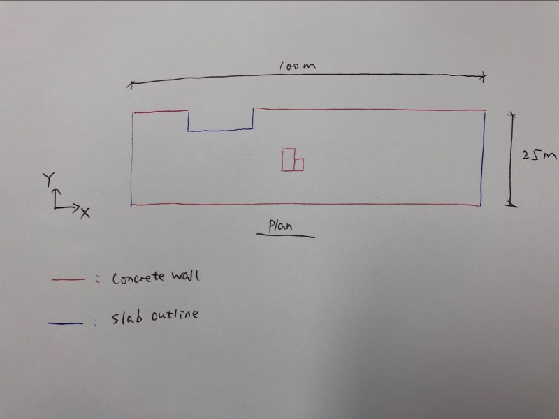
Hi Guys, I have a 7-storey building of which the plan layout looks like below. Slabs and walls are all concrete.

plan_ufwqwp.jpg


My questions are:

1. Can I use the core wall only to resist the lateral loads including wind and earthquake in Y direction? The core is slightly eccentrically located in the centre. I have built a model for this and everything seems fine: deflection is less than limit; first mode is in translation in Y direction. But I am still concerned that whether it is reliable to treat the slab as a long cantilever beam (diaphragm) to transfer the shear in Y direction to the core wall? I know the slab have strong out-of-plane stiffness but what about the connection of slab to core wall? What other analysis results should I check in my model (I am using Etabs)?

2. The first floor will be a transfer slab (or transfer beams), if I add some walls in Y direction on both sides of core walls on level 2 - level 7, which will be transferred on first floor. Can these walls be considered shear walls for level 2 - level 7 even if they don't go to the ground? (I don't think they will be significant as the stiffness of these walls will be very small if they don't continue to the ground).

3. How do you guys design a structure like this if it is not possible to have walls going to footing in Y direction on both sides of core walls?

4. Are there any good books in lateral analysis for structures like this that you guys would recommend?

Thank you.
 
Replies continue below

Recommended for you

1. I wouldn't, its flawed in many ways. Having an eccentric system with torsion and possibility of inelastic action in a single cantilevered shear wall is a recipe for bad things. Unconstrained torsional deflections may rapidly end up with collapse type drifts occurring in your gravity system out on the end walls. I think you need a secondary system (preferably walls elsewhere to at least get some coupling of the loads in y direction, though the long x direction walls may already do a good job of that. Alternatively a completely different system like portals or braced frames might be more workable for the architect out on the ends.

2. Agree you really need something going to ground on the ends. If you do what is proposed you end up with a nasty stiffness irregularity within the first storey, so you are likely to get all of your inelastic action occuring in that floor. Classic soft storey type of thing.

3. take Architect out the back and beat the crap out of them. They have to accept you need some structure, if they don't rinse and repeat beating.

 
That is a strange structure in lots of ways. I concur with Agent666 that the architect needs some drastic education. What is his exit scheme? That central core will be Swiss cheese, and I wouldn't want to work in a building where the nearest and only exit is 50 metres away.
 
I wouldn't do that at all. Not with something that heavy and long. Does it even work with accidental torsion? Why not add concrete moment frames at the far ends to control torsion?

 
Hi Agent666, Thanks for you reply.
I am not comfortable with a structure like this as well especially the slab is cantilevered this long. But on the other hand, I can't tell what's wrong with analysis result from FE analysis though. I meant, the max deflection under lateral loads is 25mm at the corners. which seems fine. So if I understand you correctly, the concerning thing is the inelastic problem. So, if the tensile stress of slab is less than f't to make sure the slab won't crack under lateral loads (or adding more reinforcement where tension is large) so it can transfer the shear to the core, will that be okay to say the structure will behave like what I model? Or is there anything that I miss or misunderstand? can you please elaborate what I need to check on the model?
I am not sure if the portal frame will work though, the stiffness of portal frame is be way smaller than the core so I doubt it will attract much lateral loads. But speaking of portal frame, can I assume the external walls (in X direction) with slab can form a portal system to resist the lateral loads in Y direction (although the wall-footing is pinned but wall-slab can be treated as rigid?)

Yes. Adding shear walls on both ends that continues to the footings are definitely my preference. But it is something not that 'common' here (Australia). I have seen too many engineering plans using flat slab with core walls as the only lateral system. Putting earthquake aside, is the original proposed plan looks okay for wind?

Thank you.
 
Hi hokie66, thanks for your reply. The X dimension is actually around 80 metres, my bad. Putting architectural issue aside, what is the exact issue for a structure like this when the deflection and strength of element seem okay after FEA?
 
Hi AaronMcD, concrete moment frames are not popular here, I have seen too many engineering plans using band beams - columns system and the columns will be transferred at other floor. Same as this one, There is no place for me to have a ground-to-roof shear walls or portal frames at both ends.
 
You are relying too heavily on your model and if you don't know the physics of the structural response and can't validate with a back of the envelope calc then it just a black box. I would say look into outrigger systems for your lateral system there is something there
 
StruTie,

I am in Australia also, and disagree that shear walls at both ends are uncommon.

80 metres is still a long floor plate, and I am surprised there are not more egress points where you can position walls. What type building? Those long walls on the sides will heavily restrain shrinkage of your slab, so be sure to address this in your design.

Agree that concrete moment frames won't help much, and that they are uncommon in Australia.

Also agree with GC Hopi about relying too much on FEA models. Get some assistance from an engineer who has done a similar project.


Hi GC_Hopi, Thanks for your reply. I am not relying on the FEA model and that's why I create this thread. I built the model to check the deflection and mode. Like I said, I am not comfortable with structure as well but I can't tell what the problem is with be for the model.
 
Hi hokie66, Thanks for your reply again.

Shear walls are common but I have seen too many plans that core walls are the only shear walls that can go to the ground. The more common structure I have seen here is flat slab with core walls, and band beam with column / wall (normally being transferred at some floor) as gravity support system.
Retail on ground floor and office above. I can position the walls but they can't go all the way down to footings. Yes. 80 metres is long plate. So the question is, how can I tell how long is okay and how long is not without running analysis? And that's why I built the model to check the deflection etc. Otherwise how do you work out the max cantilever length of the slab the core can take?
Indeed, I am not familiar with structure like this. To be honest, I am not comfortable with the structural design in Australia. For example, most, if not all, engineers here don't check the first and second mode of the structure.

 
I don't necessarily see a problem with it. Those long walls running east-west will make the structure torsionally stiff, so if the core can take the lateral it should be okay. What are the various wall thicknesses?

For a long building like this you need to check diaphragm flexibility. Running a rigid diaphragm model could be very unconservative.
 
Thanks for your reply, Retrograde. Currently the wall thickness I use is 200mm but can be increased or reduced.
 
I'm surprised that it would work with only 200mm thick walls. It doesn't feel right for a building of that size.
 
Retrograde said:
I don't necessarily see a problem with it. Those long walls running east-west will make the structure torsionally stiff, so if the core can take the lateral it should be okay.

Agree, but make sure not to skimp on the core. Make it much stronger/stiffer than it needs to be and able to handle earthquakes much bigger than code minimum.

As you can see here plenty of people will be happy to line up and shoot your design down because it looks a bit funny, so it needs to be bulletproof, not merely code compliant.
 
A plan of the core would be informative to this discussion.
 
I doubt you'll meet the torsional irregularity provisions for seismic (I'm assuming AS1170.4 has some, though last time I looked through it 15 odd years ago, it was quite behind a real serious earthquake code like we have in NZ). If it doesn't have any maybe follow NZS1170.5 provisions as a guide.
 
Some additional observations:

1) How manageable is overturning at the base of the shaft walls? I would expect challenges there.

2) I think that part of what makes this scheme viscerally bothersome is that it would seem to deny the true nature of the structure. This building is a moment frame building in the Y direction given:

a) the diaphragm flexibility combined with P-delta effects.

B) the likely core wall foundation flexibility.

C) that the lateral stiffness of your forest of columns will likely compete meaningfully with the lateral stiffness of your core wall group.

As configured, I'd expect this thing to behave like slab-frame moment frames, whether those are popular in AU or not. I'd start with that premise and then consider the implications of that, seismically and otherwise.

HELP! I'd like your help with a thread that I was forced to move to the business issues section where it will surely be seen by next to nobody that matters to me:
 
Now that I look at it more, you are probably right that moment frames won't help much. Even if you only consider shear at the wall-to-slab connection, I guess you still only get St Venant torsion so it's not as bad as it looks. Now I'm trying to figure the base - my instinct is you could still get warping torsion at the first floor unless you have a mat slab, but that would require "walking" - uplift or bearing failure at opposite - corners. Is this reasonable? I'd check corner reactions.

Ok, I was curious so I built a simple model with static lateral and torsion, and in fact one end did get overturning forces opposite the lateral forces (and opposite the torsion applied to that end). Edit - nevermind, the reactions seem to even out after ~L/5. This is too complicated for my monkey brain lol.

 
What’s the concern with torsion, given we have a pair of 100m long shear walls?
 
Status
Not open for further replies.

Part and Inventory Search

Sponsor