Tygra_1983
Student
Dear all,
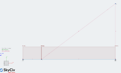
I have the following structure with its loading that I am trying to solve

I am using the stiffness method, and my MATLAB code is below:
Strangely, I am getting the correct displacements at the nodes, but when I try to retrieve the internal forces and moments I am getting incorrect answers. However, I am getting the correct axial forces, but the shear and moment are incorrect. Please observe vector A at the end of the code.
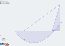
Please see, the bending moments for the structure below:

This is quite strange. Does anyone know why the moments I am getting are incorrect?
Many thanks,
Tygra
I have the following structure with its loading that I am trying to solve

I am using the stiffness method, and my MATLAB code is below:
Code:
clear, clc, close all

% Structural properties
E = 2.1E+08;
I = 1022000/100^4;
A = 620/100^2;
EI = E*I
EA = E*A
alpha = atand(30/40)
L1 = 10;
L2 = 40;
L3 = 50;
L4 = 30;
N = 12;

% Local stiffness matrix for member 1
K1 = [EA/L1 0 0 -EA/L1 0 0;
      0 12*EI/L1^3 6*EI/L1^2 0 -12*EI/L1^3 6*EI/L1^2;
      0 6*EI/L1^2 4*EI/L1 0 -6*EI/L1^2 2*EI/L1;
      -EA/L1 0 0 EA/L1 0 0;
      0 -12*EI/L1^3 -6*EI/L1^2 0 12*EI/L1^3 -6*EI/L1^2;
      0 6*EI/L1^2 2*EI/L1 0 -6*EI/L1^2 4*EI/L1;]

% Local stiffness matrix for member 2
K2 = [EA/L2 0 0 -EA/L2 0 0;
      0 12*EI/L2^3 6*EI/L2^2 0 -12*EI/L2^3 6*EI/L2^2;
      0 6*EI/L2^2 4*EI/L2 0 -6*EI/L2^2 2*EI/L2;
      -EA/L2 0 0 EA/L2 0 0;
      0 -12*EI/L2^3 -6*EI/L2^2 0 12*EI/L2^3 -6*EI/L2^2;
      0 6*EI/L2^2 2*EI/L2 0 -6*EI/L2^2 4*EI/L2;]

% Local stiffness matrix for member 3
K3 = [EA/L3 0 0 -EA/L3 0 0;
      0 12*EI/L3^3 6*EI/L3^2 0 -12*EI/L3^3 6*EI/L3^2;
      0 6*EI/L3^2 4*EI/L3 0 -6*EI/L3^2 2*EI/L3;
      -EA/L3 0 0 EA/L3 0 0;
      0 -12*EI/L3^3 -6*EI/L3^2 0 12*EI/L3^3 -6*EI/L3^2;
      0 6*EI/L3^2 2*EI/L3 0 -6*EI/L3^2 4*EI/L3;]

% Local stiffness matrix for member 4
K4 = [EA/L4 0 0 -EA/L4 0 0;
      0 12*EI/L4^3 6*EI/L4^2 0 -12*EI/L4^3 6*EI/L4^2;
      0 6*EI/L4^2 4*EI/L4 0 -6*EI/L4^2 2*EI/L4;
      -EA/L4 0 0 EA/L4 0 0;
      0 -12*EI/L4^3 -6*EI/L4^2 0 12*EI/L4^3 -6*EI/L4^2;
      0 6*EI/L4^2 2*EI/L4 0 -6*EI/L4^2 4*EI/L4;]


% Transformation matrix for member 1
T1 = zeros(6,N);
T1(1,1) = 1;
T1(2,2) = 1;
T1(3,3) = 1;
T1(4,4) = 1;
T1(5,5) = 1;
T1(6,6) = 1;

% Transformation matrix for member 2
T2 = zeros(6,N);
T2(1,4) = 1;
T2(2,5) = 1;
T2(3,6) = 1;
T2(4,7) = 1;
T2(5,8) = 1;
T2(6,9) = 1;

% Transformation matrix for member 3
T3 = zeros(6,N);
T3(1,4) = cosd(alpha);
T3(1,5) = sind(alpha);
T3(3,6) = 0;
T3(4,10) = cosd(alpha);
T3(4,11) = sind(alpha);
T3(6,12) = 0

% Transformation matrix for member 4
T4 = zeros(6,N);
T4(2,7) = -1;
T4(1,8) = 1;
T4(3,9) = 1;
T4(5,10) = -1;
T4(4,11) = 1;
T4(6,12) = 1

% Mapping from local to global using transformation matrix
Km1 = T1'*K1*T1;
Km2 = T2'*K2*T2;
Km3 = T3'*K3*T3;
Km4 = T4'*K4*T4;

% Sum up all element global stiffness matrices
Km = Km1 + Km2 + Km3 + Km4

% Application of boundary conditions
Km(:,[1,2,8]) = []
Km([1,2,8],:) = []

% Strucrtural load vector
F = zeros(N,1);
F(2) = 150;
F(3) = 250;
F(5) = 150 + 600
F(6) = -250 + 4000
F(8) = 600;
F(9) = -4000

% Application of boundary conditions
F([1,2,8]) = []

% Solving for displacements in metres
U = inv(Km)*F

% Entire displacement vector
Ux = [0;0;U(1:5);0;U(6:9)]

Ux =

         0
         0
    0.0600
    0.0000
    0.5479
    0.0449
   -0.0005
         0
   -0.0377
    0.4122
   -0.0003
   -0.0018


% Find internal forces and moments

Ax = T2*Ux % For member 2
A = K2*Ax

A =

   1.0e+04 *

    0.0171            % Axial Force
    0.0278            % Shear
    1.0000            % Bending Moment
   -0.0171            % Axial Force
   -0.0278            % Shear
    0.1137            % Bending Moment
Strangely, I am getting the correct displacements at the nodes, but when I try to retrieve the internal forces and moments I am getting incorrect answers. However, I am getting the correct axial forces, but the shear and moment are incorrect. Please observe vector A at the end of the code.
Please see, the bending moments for the structure below:

This is quite strange. Does anyone know why the moments I am getting are incorrect?
Many thanks,
Tygra
