Continue to Site

Eng-Tips is the largest engineering community on the Internet

Intelligent Work Forums for Engineering Professionals

  • Congratulations SSS148 on being selected by the Eng-Tips community for having the most helpful posts in the forums last week. Way to Go!

Correct Method to Measure TIR

Status
Not open for further replies.

DaveBNY

New member
May 20, 2015
4
Hello,

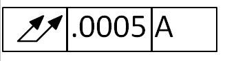
I have a question regarding the correct method to measure TIR on 2 ID's of a cylindrical part. From what I was taught and from what I believe is defined in ANSI Y-14.5, the correct way to measure the TIR on such a part is to place the part in a V-Block with an indicator on each ID and an indicator on the OD and measure the delta of the ID's while monitoring the OD.

Is this correct?
 
Replies continue below

Recommended for you

Perhaps clarify what you mean by TIR. The acronym stands for "total indicator reading," but there is actually no such spec according to the current dimensioning/tolerancing standard ASME Y14.5-2009.
The callout on the print might be circular runout, or maybe position? Or is it an older print that actually says "TIR" with a number?

Sorry to be nit-picky, but this will drive the answer. Is there a datum letter mentioned in the callout? If so, then a V-block isn't the ideal way to set up a datum. Ideally the datum feature should be fully encircled, such as with a collet.

John-Paul Belanger
Certified Sr. GD&T Professional
Geometric Learning Systems
 
No please, be nit-picky. I don't want to leave out a detail and get the wrong information.

Here is how it is on the print
TIR_k5hkty.jpg


Sorry for the large size.

This is Datum B. The ID's are .7500 =.0002 - .0001, the OD is 1.500 +- .001
 
That helps -- thanks! So the requirement can be read as "total runout not to exceed .0005, as rotated around datum axis A."

I'm not totally comfortable with your initial description because it's scanning two ID's (I take it those are the features that this total runout is tagged with), but then you're also scanning the OD (which I take to be the datum feature).

In theory, datum A should not be established with V-blocks and then scanned with an indicator (and comparing to the IDs) because any form error of the OD may be carried into the final runout measurement if the thing wobbles up and down in the V-blocks.

So ideally, datum A should be established by locking onto what they call the "minimum circumscribed cylinder." A collet, or in a pinch even a chuck, is the preferred setup for this type of datum.

The actual runout measurement of .0005 is indeed checked with an indicator. My sticking point is about the datum (but let me know if datum A is something other than the OD).

John-Paul Belanger
Certified Sr. GD&T Professional
Geometric Learning Systems
 
Datum A is one ID, Datum B is the other ID, each being a cylinder about .200 long in the ID. The OD is not a Datum.
 
OK -- sorry about that. But I still say that the V-blocks isn't ideal, because that introduces another variable. (As it rotates, any error on that OD is felt by the two IDs, which is not what the callout is looking for.)

Is there a practical way to grab onto datum A's "maximum inscribed cylinder" (expanding mandrel)? This would be the best way to simulate the datum. If not, do you have access to a CMM that might be able to do a runout check?

If not, then perhaps the V-block method is all you have. But I might try to check the roundness of that OD to ensure that it won't wobble in the V-block. Of course, checking roundness is fraught with its own issues...

John-Paul Belanger
Certified Sr. GD&T Professional
Geometric Learning Systems
 
Do you have access to something like a Taylor Hobson Talyrond? That will let you chuck on the OD but adjust the center and tilt of the work piece to get the Datum A axis aligned with the machine axis. Then you can probe the Datum B surface to determine the total run out with respect to Datum A. That is a much more accurate measurement than what you proposed in the initial post.

----------------------------------------

The Help for this program was created in Windows Help format, which depends on a feature that isn't included in this version of Windows.
 
If you have Datum A held by an expandable arbor how can you check Datum A, you have to assume Datum A is perfect correct?

Also. from what I have been able to determine, a CMM cannot check TIR correctly, so that method is out.

I just want to make sure that the parts are good. We have been checking them in the same way for a long time and all of a sudden there are issues. I believe I know what is going on but someone is questioning the measurement method even though we have been doing it the same way.
 
If you have Datum A held by an expandable arbor how can you check Datum A, you have to assume Datum A is perfect correct?
But we're not checking datum A. We're just using it as the reference axis to compare the other diameter to. (If the callout you pasted above that references A after the .0005 were tagged with datum feature A, then A wouldn't add any value; it would be the same as a circularity callout.)
Theoretically, datum A is not the ID, but the axis of a perfect cylinder derived from the ID, based on its maximum inscribed cylinder.

Also. from what I have been able to determine, a CMM cannot check TIR correctly, so that method is out.
I've heard both sides of this in the past, so I'm not sure. That might be true depending on the machine and the size of the bore being checked. One would think that if enough points are scanned on each diameter that the computer can do all the algorithms to find maximum inscribed cylinder, or roundness, or circular runout, or whatever. Dgallup's suggestion is a good one. A Talyrond or other circularity machine is kind of like a CMM but specific to roundness checks.

John-Paul Belanger
Certified Sr. GD&T Professional
Geometric Learning Systems
 
CMM will not give you accurate TIR to half a thousandth. It will spit out numbers that anyone with an agenda can use to blame whatever department they want. "It's off, bad machining." "It's right but still doesn't work, bad engineering." "It's off but inspection said it's right, bad inspection." "None of these reports match, and are not repeatable, who bought this CMM anyway?"

Also, if these are two ID's, presumably they are machined in the same setup, so why would there be TIR problems? Unless one of the ID's was reworked, or the parts shifted, or had to be flipped.

If I really wanted to know, I would put it flat on a lazy susan, center as best you can and hold down bolt/fixture if it's a small/light part. Verify the top surface is parallel with the lazy susan, then check both ID's with dial indicators. Take a video of a slow 360* spin. You could do it by chucking on the OD but then it's harder to verify that the top surface/face is parallel, which of course will affect the measurement.
 
If I understand the above description, that isn't what the print is calling for. Furthermore, are you saying that a CMM won't get it accurate within .0005" but your method will?

John Acosta, GDTP Senior Level
Manufacturing Engineering Tech


SSG, U.S. Army
Taji, Iraq OIF II
 
The tolerance block in your second post describes a total runout tolerance of .0005 to datum A, which is apparently a bore surface. You then state this .0005 total runout tolerance is applied to an OD surface based on datums A and B, which are two coaxial, offset bore surfaces. But you don't provide any definition of datums A and B.

An example of how to apply GD&T for this situation is given in ASME Y14.5-2009 figure 9-6.
 
Status
Not open for further replies.

Part and Inventory Search

Sponsor