Continue to Site

Eng-Tips is the largest engineering community on the Internet

Intelligent Work Forums for Engineering Professionals

  • Congratulations KootK on being selected by the Eng-Tips community for having the most helpful posts in the forums last week. Way to Go!

Correct use of load definition in Abaqus on surfaces with varying values

ShiningEngineer

Student
Oct 11, 2023
23
Hello dear community,

I would like to transfer a seat pressure distribution into my simulation model.

I have already been able to validate my hyperelastic material in previous studies by comparing it to experimental studies.

I would like to import my seat pressure data from a seat pressure measurement (N/mm²) into Abaqus and reconstruct it. My problem is the load definition.

Attached are screenshots that should explain my problem as an example. For a better overview and initial approaches, I have only loaded 2-4 seating data into my simulation model.

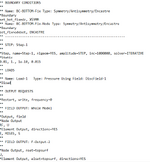
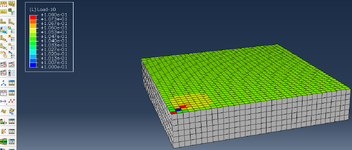
In case 1) Load via a concentrated force, I am able to transfer the seat pressure data to my simulation model after converting it to Newtons. However, the problem here is that the force is loaded via the element nodes on the surface. Neighboring elements will share the nodes, if necessary I will research again whether tetrahedron elements are more suitable. A workflow for creating an imaginary element node in the middle of each element set probably doesn't exist in Abaqus, does it?

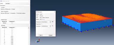
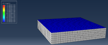
Probably the most elegant way to load a seating pressure distribution is to use a discrete field in case 2). Here, after reading the element IDs on the surface, I can directly define the pressure in N/mm² via component 1. According to the Abaqus documentation for discrete fields, the magnitude is a scaling factor and is specified as 1, did I understand that correctly? Unfortunately, my simulation starts without error messages but without results. I don't understand where my error is.

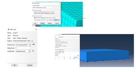
In case 3) I tried to create the pressure over the defined element surface. Here my simulation does not start at all, does anyone have a hint why?

I use the SI unit system in mm:

My model is defined in mm,
Pressure in N/mm²
Force in Newton.

I am firmly convinced that my model is realistic and conforms to units, otherwise the first case and the preliminary investigations would not provide valid results.

I would be very grateful for any advice, suggestions and, if necessary, small tips for reading in.

Best regards
 

Attachments

  • question1.pdf
    417.1 KB · Views: 2
  • question1.pdf
    417.1 KB · Views: 6
Replies continue below

Recommended for you

You could also use an analytical mapped field for pressure load to specify its magnitudes for different points (by providing their coordinates). This is independent of the node locations and interpolated between the specified values.
 
Hello, thanks for the feedback. An analytical field is then only possible via the pressure load definition right?

Which load definition do you generally recommend for this case? Concentrated force or pressure? For my application, I only want to read out the displacement later. The problem with the pressure definition is that the simulation runs, but zero force is output everywhere. In my opinion, case 2) has been created without errors, I doubt that it is due to the discrete field and that the analytical field would be the solution
 
I don't think a discrete field can be used this way. Check the input file to see how it's evaluated - you likely have an empty *DLOAD definition. A mapped field should work as expected.
 
Hi, you are right, the *DLoads definition in the .inp file is empty. But I don't understand why, because I connected the pressure load function to the discrete array I defined.

Aren't the values in "Component 1" my pressure values in N/mm²? Why would you recommend using an analytical field in this case?

Greetings


1733341712634.png1733341744516.png
 
Some combinations of prescribed conditions and discrete/analytical fields won't work even though you can assign the field as a Distribution. Abaqus/CAE should warn about that but it doesn't for some reason. Analytical fields will work though (and are quite commonly used to define non-uniform pressure).
 
Hello,

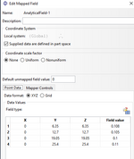
thanks for the feedback. I have now tried it via an analytical field with an example value. I have defined the coordinates so that the pressure acts on the centre of the first element. Is it correct that I enter the value in N/mm² as the field value for the pressure if I use the SI system of units (mm) and have defined my sketch in mm?
Magnitude is simply a multiplier for analytical fields, isn't it?

Unfortunately, I still have zero force in the overall model and the simulation does not give an error message..analogue to the discrete field. Unfortunately, the analytic field also does not show me any loads as can be seen in my original post in case 2) Load-Pressure discrete Field.

Do you have any other ideas on what I could look at? My logic is actually coherent and I don't see anything wrong.

Best regards and many thanks

1733345344137.png
 
Try adding more points - at least one more. Then you can go to the Visualization module even before running the analysis, switch to model and display the distribution of the pressure load as a contour plot.

Yes, MPa here and unit magnitude as a multiplier.
 
Hello FEA way,

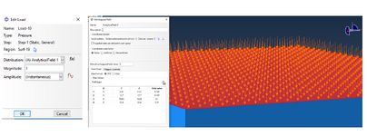
I have now defined the analytical field with 4 vectors. I have stored the value in MPa in the field value. Why are not only these 4 vectors displayed in the load function?

Unfortunately, this does not make sense for my use case of a surface-based, varying pressure distribution, or have I defined something incorrectly or misinterpreted the mathematical mapped field? It is displayed correctly in the visualisation

Do you have any other ideas on how I could implement an area-based, varying seat pressure distribution in Abaqus? Unfortunately, discrete fields and mapped fields do not work

1733407406301.png
1733407656709.png
1733407525235-png.1961

1733407705064.png
 

Attachments

  • 1733407525235.png
    1733407525235.png
    200.8 KB · Views: 27
What does this error message mean in detail? My aim is to create the pressure in the centre of each element via the mathematical field. But there is no node there, is that still allowed?

1 mesh element is 12.7 mm wide (y) and long (z).

with the mathematical field for example 1:

x=0
y=6.35
z=6.35

I would apply the pressure of 0.108 N/mm² exactly in the centre of the element.

1733412206113.png
 
What does this error message mean in detail?
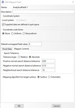
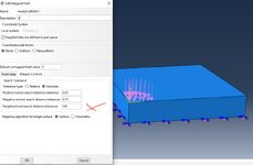
This is just a warning informing you that distance weighting was used for mapping. The problem here seems to be that interpolation goes too far and too many faces are loaded. You can control the tolerance of this interpolation in the Mapper Controls tab of the Mapped Field editor. Specifically, take a look at the "Neighborhood search distance tolerance" setting. You can use a very small value for it to disable the distance weighting so that a default value of 0 ("Default unmapped field value") is used for the faces that shouldn't be loaded. Of course, it's also dependent on the mesh density.
 
Hi,


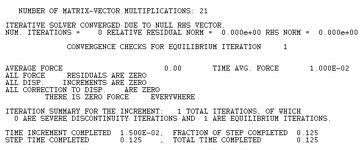
i lowered the neighborhood search distance tolerance to 10, no error warnings in simulation (completed) but i get zero force in my whole simulation model.

1733923281729.png
1733923274979.png
1733923304177.png


when i upper it to 100

1733923333953.png

i get an instant error warning in the simulation with my C3D8R elements:

1733923387365.png
 

Attachments

  • 1733923367367.png
    1733923367367.png
    2.4 KB · Views: 0
Hi there,

I changed the mapper controls from absolute tolerance type to relative and set the neighbourhood search distance tolerance to 1E+06.

I also set the default value for the unmapped field to 0.005 (it was 0 before).

In the last step I make sure in the analytical field that I define every coordinate, even if there are field values = 0. I think there was a problem when I defined the coordinates only within a field value (pressure units from the seat distribution dataset). This means that I also define out of my coordinates from my own "seat distribution system", i.e. the edge area around it (4x edge element cells around the distribution in my picture)

Thanks a lot for your input and advices so far.

In the next step, I will try to reconstruct the loaded seat pressure distribution. For this, I have considered using the NFORC1 command and reading out the force at the nodal points and then comparing it with the loaded seat pressure distribution for an initial correlation analysis. I would prefer to read out the reaction forces of the elements, as an automated comparison is easier to implement here. But I think I will have to read out the nodal stresses at the four nodes, average them and then compare them.

Greetings
 

Attachments

  • 1734598346816.png
    1734598346816.png
    119.1 KB · Views: 2

Part and Inventory Search

Sponsor