Facundo L. Pfeffer
Civil/Environmental
Hello, thanks in advance for your time.
I am trying to obtain the 'load multiplier' that will cause a structure to become unstable, using nonlinear buckling analysis with no geometrical imperfections.
I am using COMSOL software which to my knowledge does not possess this option, and I want to know if I am using the correct workaround:
- I first defined a 'load multiplier A' that applies to the stationary loads.
- I run a nonlinear static analysis using the amplified load.
- I run a linear buckling analysis on the deformed structure obtained in the previous step. Then I obtain 'load multiplier B' by solving the eigenvalue problem.
- Finally, the 'load multiplier' is obtained by multiplying 'load multiplier A' by 'load multiplier B'.
I do repeat these steps using different values of 'load multiplier A', until the final value converges.
Is my approach correct? Or am I missing some important theoretical concepts here?
Any input is much appreciated!
Extra context on how the program works can be found at but the keynotes are:
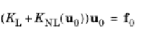
The study in COMSOL is being done by first resolving and stationary step that considers geometric nonlinearity:
Then, this initial deformation is used in the formulation of the linear buckling analysis, and the eigenvalue problem solved is:

I am trying to obtain the 'load multiplier' that will cause a structure to become unstable, using nonlinear buckling analysis with no geometrical imperfections.
I am using COMSOL software which to my knowledge does not possess this option, and I want to know if I am using the correct workaround:
- I first defined a 'load multiplier A' that applies to the stationary loads.
- I run a nonlinear static analysis using the amplified load.
- I run a linear buckling analysis on the deformed structure obtained in the previous step. Then I obtain 'load multiplier B' by solving the eigenvalue problem.
- Finally, the 'load multiplier' is obtained by multiplying 'load multiplier A' by 'load multiplier B'.
I do repeat these steps using different values of 'load multiplier A', until the final value converges.
Is my approach correct? Or am I missing some important theoretical concepts here?
Any input is much appreciated!
Extra context on how the program works can be found at but the keynotes are:
The study in COMSOL is being done by first resolving and stationary step that considers geometric nonlinearity:
Then, this initial deformation is used in the formulation of the linear buckling analysis, and the eigenvalue problem solved is:
![[glasses]](/data/assets/smilies/glasses.gif "[glasses] [glasses]")