Eng-Tips is the largest engineering community on the Internet

Intelligent Work Forums for Engineering Professionals

  • Congratulations waross on being selected by the Tek-Tips community for having the most helpful posts in the forums last week. Way to Go!

Corrupted graphics

Status
Not open for further replies.

WDAG

Mechanical
Nov 6, 2017
21
0
0
US
Hi all,

Every now and then I run across a part that gets corrupted graphics. This is on NX 11, linked with TC. All I can do right now is share screenshots of non-confidential bodies within this part. (Unfortunately I can't share the part itself because of company confidentiality... and when I make a copy of the part in order to remove confidential material, this bug goes away).

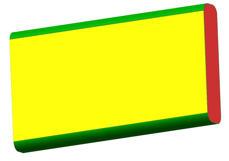
What I am showing here is a dummy part - there is a green tube, filled with red material, and a yellow film on the bottom: [Figure 1]

side_view_w9nonn.png


When the part is working correctly, it looks like this [Figure 2]

good_ui4fzq.png


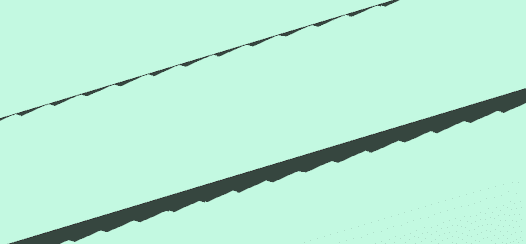
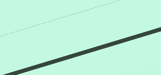
But sometimes after I do some work (most often after I invert show/hide, but also after other commands), the graphics get all all goofy - see [Figure 3] and [Figure 4]

1_la7ax0.png
2_ihuspp.png


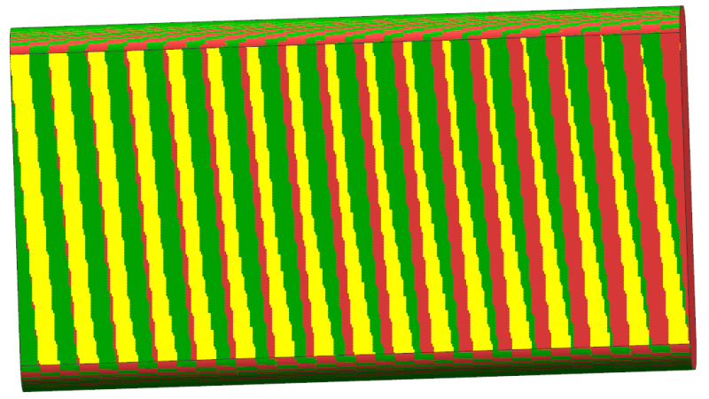
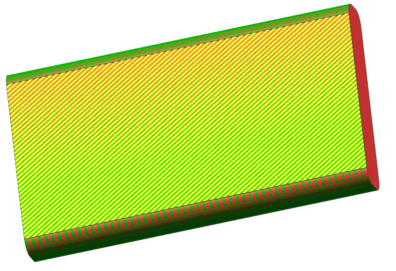
When this happens, it affects the entire view - including all parts in the assembly. I can fix this graphics issue with Right Click...Replace View...Trimetric (or any view, actually). But this is just a temporary fix, and the graphics get corrupted again after a few minutes.

Has anyone seen this issue before? I also saw this at a previous company, I think we were running NX 10 (or maybe 10.5) at that point. Is there a way to fix it, or at least prevent it from happening?

Thanks!
 
Replies continue below

Recommended for you

Did you by any chance create a duplicate body? It's possible that there are two identical bodies superimposed, one om the other, just that they are different colors, and what you're seeing is an interference of the color of one bleeding through the color of the other.

John R. Baker, P.E. (ret)
EX-'Product Evangelist'
Irvine, CA
Siemens PLM:
UG/NX Museum:

The secret of life is not finding someone to live with
It's finding someone you can't live without
 
No, it's not duplicate bodies. (For the dummy part I showed above, I made that fresh and it only has 3 bodies). Furthermore, when this graphics issue occurs, it affects the visual representation of all parts. Here's a snapshot of a single body elsewhere in the part, where the edge is all messed up:

3_rw8imw.png
 
Not to worry. Maybe it's a failing RAM chip on the graphics board. It looks like one bit is being corrupted in the geometry pipeline.

On other software you can tell the CAD program to go old-fashioned and do the pixel calculations on the CPU to see if it's the model or the GPU or the driver.
 
No, it happens on my coworkers' computers as well. It follows the part, not the computer. It only happens with this part, not with other parts.
 
Ah - OK. The other cause I've seen is that some element of the part is very far away or very large and the software is scaling the precision to account for that range. In one CAD system if one used a large enough coordinate and then translated the item the graphics would wrap-around from the maximum negative coordinate. It can be a point feature or maddeningly, the center of a very shallow arc.

In any case, is there an option to use no GPU to see if it's a GPU driver software problem?
 
It happens with just those three bodies (green/red/yellow that I showed in my first post). Nothing very far away.

Do you know how to run NX with no GPU?
 
Thanks for the link. Yes, I know all about faceting, and I convinced my company to have "View" be the default for our seed part. This is separate from that.

Alas, I may just have to deal with this until we finally update to a newer version of NX...
 
Cowski:

Yes, that looks like exactly the same issue I have! Unfortunately, when I mess around with Advanced Studio, I don't get any popups at all! Messing around with the Advanced Studio options doesn't seem to fix anything for me.

When I invert show/hide, the issue shows up, but now I can at least fix it with a Fit command. That stays, but just until my next invert show/hide.

¯\_ (ツ) _/¯

Maybe I'll just rebuild this part from scratch (it isn't too complex). At least you saw something, DenverCoder9
 
Two proposals:
1)
try the trick I wrote in Cowskis thread :
"I tried one of my old favourites, : Visualization Template. Seems to work.
RMB in the Roles Palette, - New palette
Create a new model partfile , File new - model- "ok"
With this new partfile open in the graphics, open the new palette, RMB - New Entry -> Visualization template - OK on the dialog
Change displayed part to the one with graphical glitches, drag the visualization template into the graphics window.
( maybe fit view)
This did the trick for me."

2) can you create a new partfile and then import this corrupted one into the new ?
File import part

Depending on the particular partfile, this operation might loose some data, the original file will remain unchanged. there will be a copy of the model in the new part.
the graphical settings should be from the new file.

Regards,
Tomas

Never try to teach a pig to sing. I wastes your time and it annoys the pig.:)
 
Status
Not open for further replies.
Back
Top