Eng-Tips is the largest engineering community on the Internet

Intelligent Work Forums for Engineering Professionals

Cosmetic Thread Length Configuration

Status
Not open for further replies.

DD24

Mechanical
Jun 17, 2024
6
0
0
ES
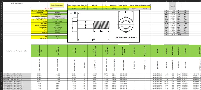
I need to create a bolt fastener with varying lengths and thread lengths. According to DIN 601 & 555 / ISO 4016 & 4034 / SABS 135, taking an M10 of lengths 35mm,130mm, 220mm, it will have thread lengths of 26mm,32mm,45mm respectively. I create a 3D model in SOLIDWORKS of 35mm long bolt (26mm thread length). Now,I auto-create the design table to include the 130mm and 220mm long bolts with 32mm and 45mm thread lengths respectively. I am sure you will agree with me that at this point,the 35mm long bolt is the active configuration. Now, my issues are:
1. When I activate any of the other configurations, their thread lengths are assigned lengths of 26mm, all of them,both in the 3D model and the design table:
1. The thread length and minor diameter dimensions are not visible in the graphics area like the shank diameter and bolt length.

Any help will be appreciated
Regards
DD24
 
Replies continue below

Recommended for you

Hie SBaugh
Thank you very much for the quick response, I thought I was the only one worried about the stuff in the Solidworks tool box. I am sorry I forgot to advise that I am on 2016, so I can not open the future version, if you can advise me waht I should do because I am keen to be able to see the various configurations with their correct thread lengths in shaded cosmetic mode and minor diameters in my 3D models and drawings.

Regards
DD24
 
Hie SBaugh
Some one has advised me that if you can send a STEP format of the file, I can use the FeatureWorks add-in to open it.

Regards
DD24
 
I saved it as a Parasolid but you will lose all the information and the DT. STEP file has the same result.

I went ahead and included the Design Table. You have to ensure you have all macros enabled under the trust center of Excel. Also, enable the ActiveX option as well. I also have the "Analysis" & "Solver" addin added in my Excel. I just want to make sure that the DT works as it is currently designed too.

I started with the SW Toolbox part file and made it into what I wanted. I removed some of their intelligence so it would work with a DT easier and control it to update the PDM data Card. There is VBA code built into this DT. Once you have all the data entered you click the "Create Configuration" button above and copies all the data to the correct cells within the DT below.

Hex_Head_Bolt-DT_bz5ewe.jpg


There is data under the image if you are curious to figure out how it works, along with the VBA code I added. Since you are losing all the data links from SW to the DT. You will have to relink them or use the DT to create your own links. Wish I had an older file to send you but I do not.

If you have any questions please post back here.


Scott Baugh, CSWP [pc2]
Mechanical Engineer
Ciholas

"If it's not broke, Don't fix it!"
faq731-376
 
Status
Not open for further replies.
Back
Top