Eng-Tips is the largest engineering community on the Internet

Intelligent Work Forums for Engineering Professionals

  • Congratulations waross on being selected by the Tek-Tips community for having the most helpful posts in the forums last week. Way to Go!

Could anyone please tell what's thi

Status
Not open for further replies.

Histor

Electrical
Mar 2, 2022
70
0
0
SG
Could anyone please tell what's this MCU (Motor Control unit) for? Does this denote a starter? Thanks.

MCU_g3qsya.png
 
Replies continue below

Recommended for you

Looks like a jumper-able input to the MCU. It would tell the MCU the status of the switches top and bottom. The MCU would be the the device that turns the motor on and off.

Edit - Hmm, both points are attached to the vertical line in the same spot. I don't think my thinking above was correct.
 
MCU is used to denote a controller for BLDC motors sometimes, but this doesn't appear to be a BLDC motor. Odd way to draw it though too.


" We are all here on earth to help others; what on earth the others are here for I don't know." -- W. H. Auden
 
Dear Mr. Histor (Electrical)(OP)4 Mar 22 12:49
"...Could anyone please tell what's this MCU (Motor Control unit) for? Does this denote a starter? "
1. MCU is NOT a starter. It does NOT have any stat/stop push-button or any SCPD or contactor or motor-thermal over-load release... etc.
2. As per the SL diagram, the motor is a 3-phase 0.25kW. It can be [switch] on/off by the withdrawable breaker. It may be is a [Motor Circuit-breaker] which is shown equipped with [thermal over-load and short-circuit] protection. Attention, it may be is a [Motor Circuit-breaker] having the thermal over-current having Class 10, 10A etc [thermal over=load characteristic. It is NOT the same as the usual MCB/MCCB over-current tripping characteristics. It may be explained in " Note B " ?
3. The MCU is connected to the line 3phases, or 3phasees+N.
It can "monitor" 3-phases LL or LL/LN voltages including frequency with (4-20mA output). With "alarm" contact for OV/UV, phase lost; voltage unbalance ets...
4. With 3/4 CTs connected to the MCU.
It can "monitor" 3-phase line and neutral currents with (4-20mA output). With "alarm" contact for OC/UC, phase lost (single-phasing); thermal over-load etc... With 4th the zero-sequency CT would be able to detect very low earth-fault etc...
5. A MCU may have all or some of the functionalities, depending on the load/operational requirement.
Che Kuan Yau (Singapore)
 
@ Dear Mr. LionelHutz (Electrical)7 Mar 22 21:24
"...Looks like a meter to me. 5VA CT's aren't enough to drive a protection relay..."

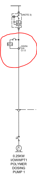
1. The MCU can be a " meter" with functionalities to read Voltages, Frequency , Currents, Wattage, VA, var , Power-factor, Voltage unbalance, Earth-leakage current etc., etc. It is also possible to be able to output 4-20mA for remote "monitoring",
2. In addition, it can be an "Alarm" device with set value for OV/UV, Of/Uf, OC/UC, Single-phasing, Phase reversal, Ef etc., etc,
3. A MCU, depending on the number of functionalities; can be a very small "box" say 144x144x100 mm. It contains only small electronic components, no contactor, no thermal over-load heating element, no rotating disc such as used in kWh meter or mechanical rotating disc for over-current time delay tripping etc., etc.
4. The Class 1 5VA is far enough for current [detection] purposes. The energy to drive the protection relay is taken from the power supply. Note: there is NO heavy burden mechanical rotation disc to drive.
Che Kuan Yau (Singapore)
 
Che - You think I don't know what electronics are, or what a panel meter is? You obviously don't deal with 5A CT circuits. 5VA 5A secondary CT's can drive a panel meter no problem, but they can't properly drive a protection relay.
 
Histor,
To me, the top line to MCU is to provide 1-phase aux supply to MCU and the bottom line is CT secondary connection to MCU to monitor / control the Motor.
It is possible that the top line actually is three phase or Three phase and neutral connection to the MCU in which case MCU can provide voltage unbalance protection as well.
4 on top of the CT symbol suggests that the MCU is getting current from all phases as well as from neutral. I doubt about the neutral CT as it is not relevant in case of three phase motor feeder. Core Balance CT is more of a standard with motor feeders to provide sensitive earth fault protection.
 
A long shot. Possibly a combination of P&ID and electrical drawing. Motor application claims Polymer dosing pump. The motor part# i/oWWpt may denote waste water treatment. At the top of the drawing, could that be a exploded view of the MCU functionality? A search online led to the speculation it may be that. The line at top could be comms, 24vdc power and control feeding all components needing power and comms. A in-line flow meter/transducer feeding its signal to the MCU (measurement control unit) for monitoring product from the dosing pump. If you can see the diagram as both P%ID and wiring together, where not all liquid hardlines are present to/or from the motor dosing pump it may allow some liberties in the speculation as to what the drawing is representing. Good luck
 
 https://files.engineering.com/getfile.aspx?folder=144a8ab3-09aa-4e55-a8fb-acf8cfc1578f&file=dosing_pump_controller_application.pdf
Status
Not open for further replies.
Back
Top