Eng-Tips is the largest engineering community on the Internet

Intelligent Work Forums for Engineering Professionals

  • Congratulations waross on being selected by the Eng-Tips community for having the most helpful posts in the forums last week. Way to Go!

Coulomb friction: Theory vs Abaqus

Status
Not open for further replies.

drennon236

Civil/Environmental
Mar 27, 2020
102
NO
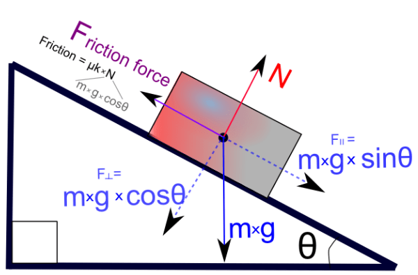
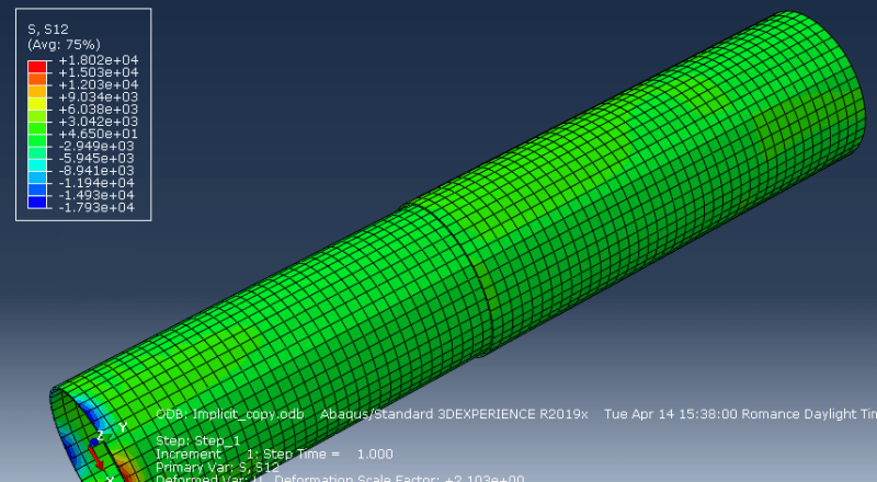
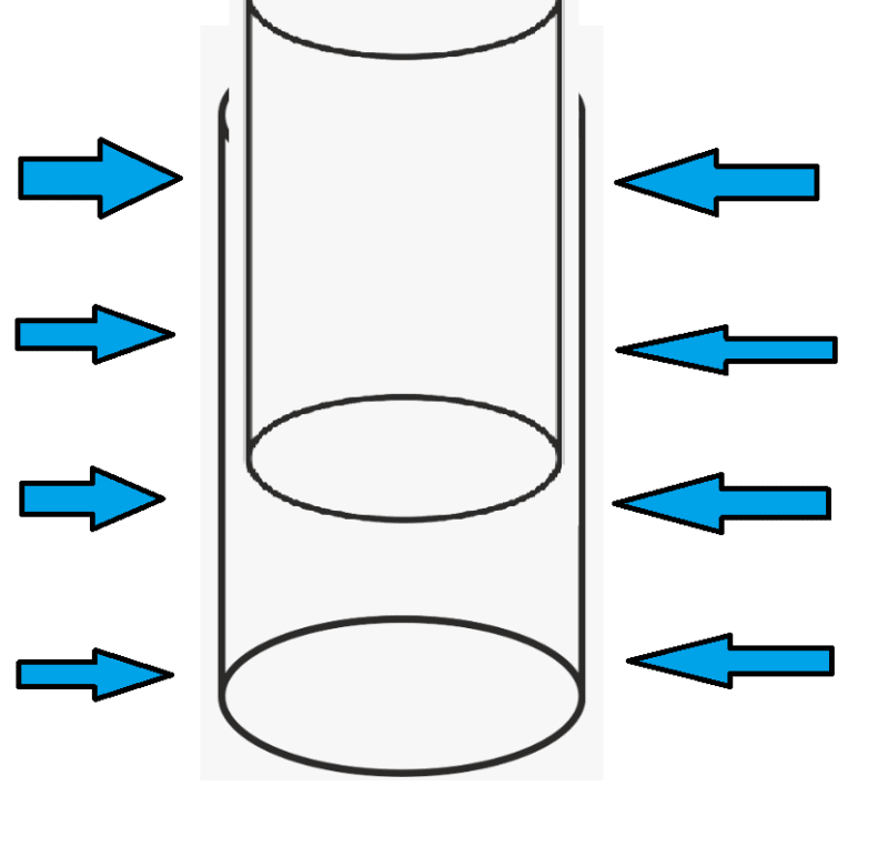
I want to find the equivalent friction force in the first figure, in the two cylinder that are in contact with each other in the second picture. Is it correct to look at S12 in Abaqus? Should I look at something else since S12 is shear (MPa) and units are different than the friction force (N)? I wanna do this to make sure the friction force I get in my cylinders is according to theory.

Bank_ufwkbs.png

93434598_1406649976189813_8850110220299403264_n_ozpfb6.png
 
Replies continue below

Recommended for you

You can use specialized contact output for that. Check variables CSHEAR (frictional shear stress) and CSHEARF (frictional shear force).
 
Do you know how to get these specialized contact outputs? Can I get it for Dynamic, Implicit step? And C3DR8 elements?
 
They can be found in Field Output Requests —> Contact. Just select CSTRESS (CSHEAR is part of it) and CFORCE (CSHEARF is part of it).

You can also select CSTRESS in History Output Requests but CFORCE is not available there (total force due to frictional stress CFS can be used instead).

Sure, they can be used in this type of analysis and with these elements.
 
FEA way; how would you suggest going about comparing CSHEAR/CSHEARF with analytical results? I want to make sure the friction force/stress I get in the cylinders is according to theory, but I am not sure which theory to compare it with.
 
Create a contour plot of CSHEARF but make sure that you select proper component of this variable (there are three available: CSHEARF1, CSHEARF2 and CSHEARF3, the choice depends on the orientation of the model in current coordinate system). In addition you can plot CSHEARF —> Magnitude (resultant of these 3 vectors).

These variables can be compared with analytical value of the force of friction (calculated based on applied load and coefficient of friction).
 
The applied load; if I apply pressure to the cylinders, will the load then be pressure multiplied with the area?
 
Yes, you have to multiply applied pressure by the area to get force for these friction calculations.
 
I read online that the change from static to dynamic friction will probably not be close to analytical, but should quickly approach it once the movement is started. Would you happen to know why? And can I simulate movement by having a displacement boundary condition.
 
There are separate coefficients for static and kinetic friction while in Abaqus you normally define single friction coefficient. However it’s possible to use more advanced friction models (check the Static-Kinetic Exponential Decay option).

Sure, you can use displacement control instead of force control. In fact, the former can significantly aid convergence in analyses with contact.
 
Force control would be applying normal pressure? For example hydrostatic pressure to the cylinders to activate coulomb friction between the two cylinder. They are supposed to be in close contact. And then make sure the CSHEARF output somewhat match the analytical ?

inelastic_uq8v9w.png


What would then displacement control be? Displacing the outer cylinder for example vertically downwards? - because then there is going to be minimum amount of CSHEARF, because there is no normal force to activate the coulomb friction.
 
Generally speaking, displacement control is preferred method in FEA but of course it’s not always possible. It all depends on the goal of the analysis and adopted loading scenario. If you only want to find the friction force then you will most likely need pressure to establish contact (there are other ways to achieve this though, we discussed some of them in your previous thread). Then you will have to cause some slip between these two surfaces. You can use prescribed displacement in vertical direction for this purpose. Or enable gravity.

There is a comprehensive document about modeling of grouted joints that you may find useful. Search for "DNVGL-RP-0419 Analysis of grouted connections using the finite element method"
 
Status
Not open for further replies.

Part and Inventory Search

Sponsor

Back
Top