Continue to Site

Eng-Tips is the largest engineering community on the Internet

Intelligent Work Forums for Engineering Professionals

  • Congratulations pierreick on being selected by the Eng-Tips community for having the most helpful posts in the forums last week. Way to Go!

Counter Flow Plate Heat Exchanger Inlet / Outlets

Status
Not open for further replies.

Jack Benson

Industrial
Jul 11, 2023
101
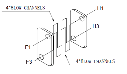
We currently use a plate heat exchanger that is designed as follows

Current_HX_Port_Layout_psb3bf.png


F2 is the HOT INLET
H3 is the COLD INLET

We have a problem that we cannot attach elbows directly to each of the 4 ports as the gap between the centres on the ports is only 50mm

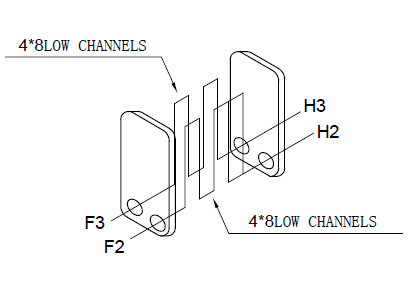
Our Heat Exchanger supplier has said we can get the same performance with the following design and it will solve the issue we are having with attaching elbows to each inlet/outlet:

Proposed_HX_Port_Layout_hfjokj.png


In this design, they say:

F1 is the HOT INLET
F3 is the COLD INLET

I can see along each plate the flows are in the opposite direction to each other.

They say that the performance of both layouts is the same.

Can anyone let me know if this is true?

COLD temp is between 6-20C depending on the time of year
HOT temp is approx. 37C

The liquid is water flowing at about 6 litres per minute.

thank-you in advance
 
Replies continue below

Recommended for you

Why have they changed the inlets?

H3 should be the cold inlet in both

Remember - More details = better answers
Also: If you get a response it's polite to respond to it.
 
I do not know why they have changed the INLETS on the new proposed layout.

I queried it with them and they insist that this is correct

Proposed_HX_Port_Layout_yjne9p.png


F1 is the HOT INLET
F3 is the COLD INLET


In the original design, the counter flow is from LEFT to RIGHT.

In the proposed design, the counter flor is from TOP to BOTTOM.
 
At those sorts of delta T the performance might be pretty close, but doesn't look right to me.

Plate HXs work as sets of plates adjacent to each other.

First one is a counter flow with hot and cold going from different sides.

Second one is concurrent flow with both flows going from left to right.

Remember - More details = better answers
Also: If you get a response it's polite to respond to it.
 
Hi,
Did you ask a calculation note from vendor and in writing reply (email)?
Can you supply more information about the fluid (flows, temperature profile, liquid properties (density, specific heat, heat transfer coefficient) and area of the heat exchanger to review the calculation (data sheet or spec sheet will be great)?
Pierre
 
yes the second one is concurrent flow from right to left, but counter flow from top to bottom

the liquid on both sides is water

COLD temp is between 6-20C depending on the time of year
HOT temp is approx. 37C

Flow rate is 6 litres per minute
 
 https://files.engineering.com/getfile.aspx?folder=e98332ec-7933-4751-bba4-de6b94bf4239&file=T0476-4074-HC020G-65(4X8.4X8)-3.0-H Model (1).pdf
This is the calculations that they did for the original counter flow heat exchanger.

They say it is the same for the heat exchanger with the orders in the new positions even though is concurrent flow
 
Hi,
No data sheet, calculation note to support the design of the HX?
Note: I understand it's a Chinese company based in SHANGHAI, may be some difficulties to communicate with them?
Pierre
 
Hi,
Using your data sheet (word) I confirm that the counter current design will have outlet temperature of 8,03 C and 36.05 C but for the co current design you should have a temperature of 22 C both outlets.
The supplier should submit a formal calculation note to support the co current design.
Pierre
 
I was going to ask what the purpose of the HX is?

Is it is heat up the cold water or cool down the hot water?

What temperatures do you want?

Not that of course if the cold water side is up to 20C, then this will impact the two temperatures, probably changing them to 22 or 23C for counter current and ~28C for co current flow.

An approach temp of 2C looks quite low, but maybe correct for plate exchangers where the flow seems to be quite low for the surface area.

Remember - More details = better answers
Also: If you get a response it's polite to respond to it.
 
After querying it again the HX supplier said they made a mistake and the concurrent flow design is much lower performance.

We have tested the original counter flow design and were happy with the results, although I am yet to test with a cold supply @ 6C so I can't confirm the exact performance.

I really appreciate all your help.

I dodged a bullet.
 
Status
Not open for further replies.

Part and Inventory Search

Sponsor