Continue to Site

Eng-Tips is the largest engineering community on the Internet

Intelligent Work Forums for Engineering Professionals

  • Congratulations KootK on being selected by the Eng-Tips community for having the most helpful posts in the forums last week. Way to Go!

COUNTERBALANCE SYSTEM BENCH TEST

Status
Not open for further replies.

BEMPE16524

Mechanical
Feb 17, 2008
327
Hi Everyone,

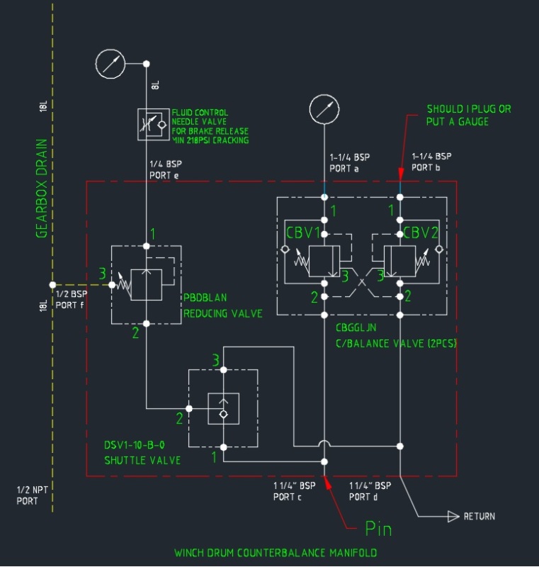
I need some advice. My purpose is to set up the counterbalance valve (CBV) pressure to ~3500psi since we don't know what is the factory setting.
I will use enerpac hand pump to give pressure. So, the question is can i plug or put a gauge on port b? Or must i put load on both port a and b?
CBV1_iyzxsk.jpg


R.Efendy
 
Replies continue below

Recommended for you

with respect...

I don't think you have a good understanding of what you are trying to do here.

If you want to know the setting of the motion control valves...they are not counter balance valves, they have a pilot supply to them, then you need to supply pressure to port a or port b.

The pressure you see at the hand pump is the setting of the valve.

You also need to know the pilot ratio. That is the pressure required on the a line in order to open the valve in the b line. And vice versa...

Ports c and d will need to be plugged if you don't want to have oil on the floor...

To confirm the pilot pressure, you will need to have pressure at port c and b. Holding constant pressure at port b at about 10% below the cracking pressure, increase pressure at port c until the pressure in port b starts to drop off.

It's not easy to do and it is easier to check these things when you have load under gravity sitting on the cylinder connected to the motion control valve or over centre valve...you back the valve off until the load started to move. Then apply a pressure to pilot supply and see what pressure was required to open the valve.

The pilot ratio is the difference between the cracking pressure of the valve and the pilot pressure needed to open it remotely. Pilot ratio is normally 1.5 : 1 or 2 : 1 or something like that...

Higher pilot ratios make things go unstable...so keep it as low as possible.
 
HPost,

With all respects, i admit my lack of knowledge in hydraulic.
Can you please sketch in a simple way of how should i do the valve setting if you don't mine.

R.Efendy
 
First thing to say is that the Sun Hydraulics part numbers that you have on the drawing tell you much of the what you need to know...

For example..

Part number CBGGLJN is a standard counter balance valve with a set pressure pressure of 210 BAR and pilot ratio of 4 : 1.


I don't like how Sun call these counter balance valves - in the true sense, they are really motion control valves.

Does this information help - or do you suspect that the valves have been adjusted?

Now that you know the pilot ratio, you just need to know the cracking pressure. That should be 210 BAR. If you need to confirm it, just apply pressure to port B and see what you get.
 
That make sense, one more problem is that, sometimes (on the PBDBLAN reducing valve) the winch will slip after we stop the pressure in.
Meaning that there are still pressure on the brake release line.
Other than adjusting the reducing valve, is there any kind of valve that will ensure the line has zero pressure so that the brake will engage again?

R.Efendy
 
The choke / check valve that you have on the brake release line...

Are you using that to control the release of the brake or the application of the brake?

As drawn, it allows free flow to release the brake and will control the flow when the brake cylinder is being pushed back by the spring or counter weight on the brake.

If the valve is as drawn, it will need to be fully open.

If need be, you can turn the valve around to give speed control on the release of the brake and faster return.

If that is still not quick enough, then you need to install a 3 port 2 position valve that dumps the brake line pressure when the brake is being applied.

The drain through the shuttle valve may be the limiting factor. you will have to run some checks to see what part is restricting the cylinder flow.

 
It's to control the brake release.
I have no idea that the valve can be reversed since we normally follow the arrow on the symbol for the direction.
I think i made a mistake on the symbol. the check valve symbol on the needle valve should be the opposite direction.

the manual for the PBDBLAN state this:
-Full reverse flow from reduced pressure (port 1) to inlet (port 2) may cause the main spool to close. If reverse free flow is required in the circuit, consider adding a separate check valve to the circuit.
So, i assume i can add a check valve in between port 1 and 2 to increase the flow rate.

Now i have 2 solutions from your suggestions (the third idea may be difficult because we have fabricated the manifold) and one from what i read in the manual.

R.Efendy
 
yes, you can add a check valve that will send oil around the reducer and that may help increase the speed. However, that may not be enough as you don't know for sure if the reducer is the limiting factor.

To get the speed you need, you may have to drain the cylinder to tank. In which case you need a valve as described above - 3 port / 2 position.

This could be a pilot operated valve that is closed when operating the brake, then opens to allow the cylinder to drain. In doing this, you may find that the cylinder is too quick and you may need another flow control valve.

Systems like this are highly susceptible to viscosity changes - what works well in warm ambient conditions can go really slow in cold weather. I have seen many winches fail as the cylinder accelerates the brake mechanism too hard and causes it to fall apart. It can be a tricky balance...
 
i understand what you mean. i gonna go to see the manifold testing tomorrow and i shall see how fast the pressure drop on the brake line.

R.Efendy
 
Your assembly without a check valve is dangerous. In order for the main spool to open the connection between 1 and 2, the pressure in the brake must drop by leakage in the main spool games. With a cold oil and therefore a tiny leak, the brake can take 10 seconds to close. Mount a valve by-pass as is always done on a winch brake jack.
Read the SUN provider documentation:"Full reverse flow from reduced pressure (port 1) to inlet (port 2) may cause the main spool to close. If reverse free flow is required in the circuit, consider adding a separate check valve to the circuit".
 
73lafuite,

Yes, i notice that on the manual and has put it into concern.
Meanwhile, we did the test on the system and so far the stand alone manifold can assure a free return of the brake line. The difficult part is to get a full test due to the HPU/Winch is not with us currently.

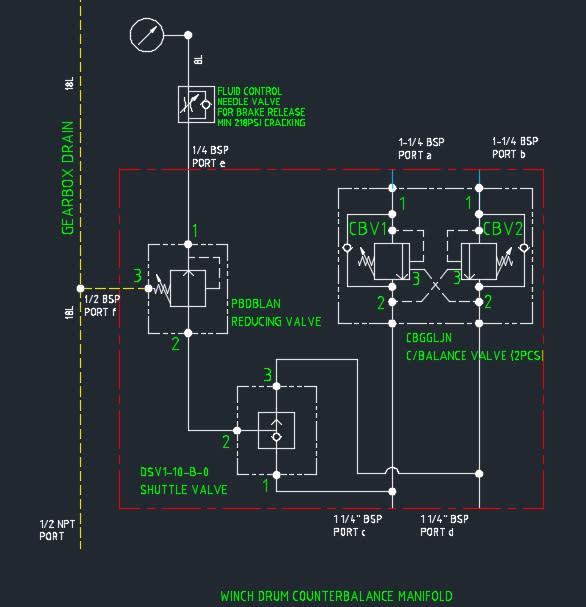
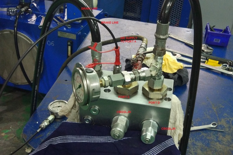
Here's how we did the test:
CBV1_zpmqcb.jpg

Required Pressure: 273 Bar (Setting Pressure) (Supply and output)
Cracking pressure for CBV1 = 273/4.5
= 60 Bar (this is the minimum pressure supply from Port d to allow return flow from the winch to Port a)

1. Connect Port d with supply pressure in our case 60 Bar supply with a pressure gauge.
2. Connect Port a to air supply (air compressor unit) with ball valve.
3. Connect Port f to a pressure gauge.
4. Plug Port b.
5. Open Port c.
6. Now start the main HPU and increase the pressure on Port d until it reach 60 Bar. At the same time open the compressed air supply.
7. Adjust the CBV1 until the air from the Port a is release to Port c simultaneously when the pressure reach 60 Bar at Port d.
8. Turn the CBV CCW to increase the pressure.
9. Once the pressure is set, stop the air supply.
10. Now set the PBDBLAN reducing valve to 50 Bar. Do not off the main HPU yet.
11. Once PBDBLAN is set, quick release the main pressure and make sure the pressure on Port f drop to zero simultaneously with the main pressure. That is to ensure that the brake is working fine.
12. Now you can off the HPU, and do the setting for the CBV2. Supply the 60Bar pressure to Port c and connect the air supply to Port b.
13. Repeat Step 3-11.

CBV2_fjvrf2.jpg


R.Efendy
 
Hello,

Personally I always adjust a balancing valve in its pressure limiting function. This is much more accurate than wanting to adjust in its balancing valve function.

So just connect c and d directly to the tank. Note 1: This is what your distributor should do when you do not order it. Note n ° 2: It is obvious that you work in open circuit, that is to say not in closed circuit with pressure boosting.

To set CBV1: put a plug on b and send a small flow of 2 to 10l / min in a and screw the setting until read 273bar in a. This means that the maximum load on the winch would be 273 / 1.3 = 210bar.

Do the same thing for CBV2 by inverting a and b.

Cordially.
 
73lafuite,

Thanks for your advice. Will put that into consideration as well.

R.Efendy
 
Status
Not open for further replies.

Part and Inventory Search

Sponsor