Continue to Site

Eng-Tips is the largest engineering community on the Internet

Intelligent Work Forums for Engineering Professionals

  • Congratulations KootK on being selected by the Eng-Tips community for having the most helpful posts in the forums last week. Way to Go!

Couple two node/element sets at a later step/ activate connector elements at a later step

Status
Not open for further replies.

anandv1603

Automotive
Jul 2, 2015
13
Hi all,

I am assembling a seat cover to the seat structure and only at the end step i need the seat cover to be coupled to the seat structure (in ABAQUS standard 6.13.)

So I would like to know is there is any possibility of node to node contact?

I know there is a possibility to link them using connector elements.

But how to activate the connector elements only for the last step?


Replies continue below

Recommended for you

Hi,

Abaqus does not have option to active/deactivate connector elements but you can use field variable to get similar behaviour.
Connector element will be active always for all steps but it will not generate any force.
Lock condition depends of field variable, as long FV1=0.0 the is no lock condition, for FV=1 any velocity will lock the element.

Code:
**
**------------------------------------------------------------------------------
**    MODEL DATA
**------------------------------------------------------------------------------
**
*ELEMENT, TYPE=CONN3D2, ELSET=connector
 1, 1, 2
*CONNECTOR SECTION, ELSET=connector, BEHAVIOR=connector-BEH
 AXIAL

*CONNECTOR BEHAVIOR, NAME=connector-BEH
*CONNECTOR LOCK, DEPENDENCIES=1
** disp, disp, force, force, vel, vel, temp, FV1
       ,     ,      ,      ,    ,    ,     , 0.0
       ,     ,      ,      , 0.0, 0.0,     , 1.0
**
**------------------------------------------------------------------------------
**
** amplitude for *FIELD
*AMPLITUDE, NAME=field-AMP
**          time,              FV
             0.0,             1.0
          1000.0,             1.0
**
**------------------------------------------------------------------------------
**
** set node for *FIELD
*NSET, NSET=connector-FV-NSET, ELSET=connector
**
**------------------------------------------------------------------------------
**
** initial conditions for FV1
*INITIAL CONDITIONS, TYPE=FIELD, VARIABLE=1
 connector-FV-NSET, 0.0
**
**------------------------------------------------------------------------------
**    HISTORY DATA
**------------------------------------------------------------------------------
**
*STEP
**
*FIELD, VARIABLE=1, AMPLITUDE=field-AMP
 connector-FV-NSET, 0.0
**
*END STEP
**
**------------------------------------------------------------------------------
**
*STEP
**
*FIELD, VARIABLE=1, AMPLITUDE=field-AMP
 connector-FV-NSET, 1.0
**
*END STEP
**

Regards,
Bartosz


VIM filetype plugin for Abaqus
 
Thanks for the suggestions Bartosz and IceBreakerSours!!!

However when i tried the above coding with some other displacement driven conditions, the simulation gives "time increment required is less then minimum specified" eror. When i change the connector element to JOIN, the simulation works but the connectors are active from the beginning.

I would like to mention that the dependencies parameter in CONNECTOR LOCK is available only in ABAQUS explicit. But i use ABAQUS implicit, so i have used the following code.

*CONNECTOR LOCK, COMPONENT=1, LOCK=ALL
0., 0., 0., 0.
*CONNECTOR LOCK, COMPONENT=2, LOCK=ALL
0., 0., 0., 0.
*CONNECTOR LOCK, COMPONENT=3, LOCK=ALL
0., 0., 0., 0.

The four zeroes represent the Lower and upper boundary displacement limits, Lower and upper boundary force limits respectively.

My idea is that when the Connector is active, any small movement of the elements in x,y or z direction should lock the element which is exactly what i want in my simulation.

Please tel me where could i be wrong??
 
Hi,

the Lower and upper boundary displacement limits
Not displacement but connector position (length).
If your connector has initial length 10mm and you put here 0 the connector is lock from the beginning of simulation.
If you put 15 your connector will be lock after 5mm of displacement.

My idea is that when the Connector is active
And it is, but it is also lock from the beginning as explained above.

Just for my understanding. You have two nodes with specific distance and you move them to one position with *BOUNDARY.
In final position the nodes are in the same position (distance between them is zero) and then you want to "lock" the nodes together?

Idea 1)

Code:
**
*CONNECTOR LOCK
** lenMin, lenMax, forceMin, forceMax
      0.0,       ,         ,

Connector will be lock when you get 0.0 length.
Please be aware that value of zero and no values are not the same in *CONNECTOR LOCK.

Idea 2)

Use *BOUNDARY in one step and *CONNECOTR MOTION, TYPE=VELOCITY in next.
Connector zero velocity is like lock plus *CONNECOTR MOTION can be turn on/off between steps.

Code:
**
**
*STEP
** move nodes to positon
*BOUNDARY, TYPE=DISPLACEMENT
 ...
**
*END STEP
**
**------------------------------------------------------------------------------
**
*STEP
**
** reset boundary conditions
*BOUNDARY, TYPE=DISPLACEMENT, OP=NEW
**
** lock connector
*CONNECTOR MOTION, TYPE=VELOCITY
 connector-ELSET, 1, 0.0
**
*END STEP

I think you can use *CONNECTIR MOTION instead *BOUNDARY as well.

Regards,
Bartosz


VIM filetype plugin for Abaqus
 
Hallo Bartosz,

Thanks again.. You have perfectly understood my problem..

From your comments, i understand that in case of using a *CONNECTOR LOCK as stated by you, i dont need to deactivate it since it locks only when the condition is satisfied. So i dont need a field variable.

Now, I tried the following.
[ul]
[li]Define an AXIAL CONNECTOR between two corner nodes of two sheets 30mm apart in Y-axis i.e., the piston in the connector element is along y-axis.[/li]
[li]I move one sheet in the y-axis (30mm) fixing the other.[/li]
[li]Then in the *CONNECTOR LOCK i define only the U.B.Pos for component 2] (y-axis) and leave all others blank using the following code.
*CONNECTOR LOCK, COMPONENT=2, LOCK=ALL
0.,[/li]
[/ul]

My understanding is that when the length is zero in component 2 which is y-axis then the lock is activated.

I tried the following values in the L.B.Pos box and got the following results:
[ul]
[li]with 0 - No connection established at all.[/li]
[li]with 5,15,35 - Connector established form the beginning.[/li]
[/ul]

I tried the same with U.B.Pos alone in component 2. It works but stil has some error

First step they come together. Second step i move them to the seat structure and fix the outer edge nodes . Third when i release the boundary conditions on these nodes keeping only the boundary conditions on the outer edge nodes but there is a distortion. It is something to do with the connector motion option. I am unable to figure it out.

I have attached the input file of the my trial model.

Kindly help me out....


 http://files.engineering.com/getfile.aspx?folder=a6de22fd-17f9-441d-8751-8dc257db890c&file=trial1.inp
Hi,

•Define an AXIAL CONNECTOR between two corner nodes of two sheets 30mm apart in Y-axis i.e., the piston in the connector element is along y-axis.
•Then in the *CONNECTOR LOCK i define only the U.B.Pos for component 2] (y-axis) and leave all others blank using the following code.
*CONNECTOR LOCK, COMPONENT=2, LOCK=ALL
0.,

AXIAL connector has only one component active, COMPONENT=1.
It is axis passing through both connector element nodes, so it is not necessary along any global axis.
I guess you should have some warning message that you use lock with not active component.

I run your model with CP1 (connector length) output and I see the connector never reach length of 0 but 1.0e-03 so it can not be lock with
zero value under *CONNECTOR LOCK.

I made two models:
1. with *CONNECTOR LOCK (I used value of 0.01 not 0.0)
2. with *CONNECTOR MOTION

The problem is that both models have no convergence in 3rd step.
It doesn't have to be related to connectors because your model with out connectors have the same problem.

Any reason you cannot use Abaqus/Explicit? At least there will be no problem with convergence.

Regards,
Bartosz


VIM filetype plugin for Abaqus
 
Hallo Bartosz,

Thanks a lot for the input files. I tried the same in my main model.

The distance between the nodes is 42.456

When i give 0,0.05,1 as the L.B value..i get the same result as i get without LOCK connection.
When i give 20 as the L.B.Value..the LOCK is activated after the two parts move halfway towards each other.

So, in principle the LOCK is working but not for zero or small distance between them... What may be the reason?

Does the component represent the Axial direction always?? becoz in my main model the axial elements are not aligned to the nodal coordinate system.

Is there any other ways to LOCK them using other CONNECTORS?

NOTE: The connector MOTION moves the nodes away from each other...so i am unable to find out what is happening

Kindly suggest your opinion..

Thanks again
Anand
 
Hallo Bartosz,

I have found that there was a mistake in my model definition. So now the connectors are working. Hopefully i wouldn't have to bother you again...

THANKS a lot for your time and help!!!!!

Regards,
Anand
 
Hallo Bartosz,

The connectors work well. Now my question is that is it possible to lock only one direction of the connector component? i.e., i am pressing the seat cover which is at 50mm over the seat cushion. once the gap reduces to 40mm the seat cover should be fixed to the seat cushion. However, i just want it to be fixed so that the seat cover cannot move away from the seat cushion but it should be free to move towards the seat cushion.

This is simply like a piston configuration. My upper limit is the lock criteria 40mm. My lower limit is 0mm meaning the seat cover can touch the seat cushion. I dont think i can use connector stop since the initial gap/connector length is 50mm which is more than my required upper limit.

I think this is possible when i activate the connector only when the connector length is less than the upper limit and hence use the stop option. May be using the connector motion which you explained earlier. But unfortunately i am little confused how this connector motion actually works like to activate the connector when the length of the connector reaches a specific value.

Kindly suggest your opinion and provide more clarity on this connector motion or any other options.

Thanks again!
anand
 
Hi Anand,

I agree with all your doubts. *CONNECTOR STOP is not an option in this case.
I think Abaqus does not have simple functionality you are looking for but I have one idea.

The idea is to have two characteristics (one for unlock phase and one for lock phase).

Code:
**
*CONNECTOR BEHAVIOR, NAME=conn-BEH, EXTRAPOLATION=LINEAR
*CONNECTOR CONSTITUTIVE REFERENCE
 40.0
*CONNECTOR ELASTICITY, COMPONENT=1, NONLINEAR, DEPENDENCIES=1
**     force [N],      disp [mm], , FV1
             0.0,           -1.0, , 0.0
             0.0,            0.0, , 0.0
             0.0,            1.0, , 0.0
**
             0.0,           -1.0, , 1.0
             0.0,            0.0, , 1.0
          1000.0,            1.0, , 1.0
**

Next the characteristic is switch from unlock to lock at time you get 40mm of length using field variable.

Code:
**
*NSET, NSET=field-NSET, ELSET=conn
**
*AMPLITUDE, NAME=field-AMP
**      time [s],        FV1 [-]
         0.0e-03,            0.0
        50.0e-03,            0.0
        51.0e-03,            1.0
      1000.0e-03,            1.0
**
*FIELD, VARIABLE=1, AMPLITUDE=field-AMP
 field-NSET, 1.0
**

Disadvantage of this approach is that you have to know time when you have 40mm a priori.
In my test model initial lengh is 50mm so 40mm of lock condition I have after 10mm of deformation and I assumed it is at time 50ms.

Code:
**
*AMPLITUDE, NAME=load-AMP
**      time [s],      disp [mm]
         0.0e-03,            0.0
        50.0e-03,          -10.0
        75.0e-03,          -20.0
       100.0e-03,            0.0
*BOUNDARY, TYPE=DISPLACEMENT, AMPLITUDE=load-AMP
 2, 1, 1, 1.0
**

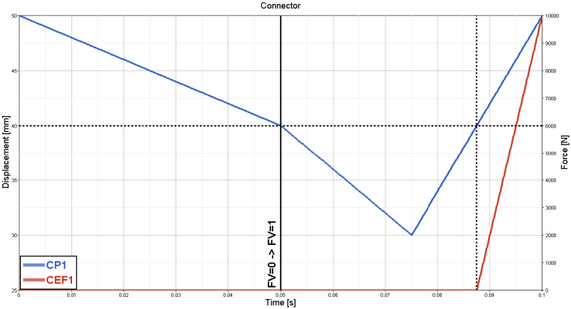
To do not have this limitation you can use sensor output + UAMP/VUAMP subroutine to control field variable.

Lets take a look for results from my simple model.
aaa_bjsc0x.png

Characteristic switch (change value of field variable from 0 to 1) is made at time when I have 40mm for first time.
No force is generated until I got 40mm once again, after this time high resistance force is generated.
I am using boundary conditions so connector deformation is not stopped but it will be for case where connector deformation is controlled by force.

My test model is attached as well.

Regards,
Bartosz


VIM filetype plugin for Abaqus
 
Hallo Mr.Bartosz,

You just seem to know a solution for anything i ask. This was a great help indeed from your side. Thanks a lot. But unfortunately i have different regions with connectors of different length so it is really not possible for me to use that time method. Anyhow thanks again!!!

Just out of curiosity, is there any book or tech papers that i can go through to know more of these intensive ways of using such complicated options in ABAQUS???

Regards,
Anand
 
Hallo Mr.Bartosz,

Hi.. I see that one could remove and add elements using MODEL CHANGE. So i am planning to use it to weld two node sets together: one from each edge of two seat cover pieces.

As i stated earlier they are far apart initially.. i bring them closer using displacement conditions during which they press a seat foam present between them. when they are close enough i add the WELD CONNECTORS and remove the displacement boundary conditions from those node sets. However, the simulation dont converge and it runs upto the same time increment even if i use BEAM CONNECTORS in place of WELD.

The same concept works in another region where there is not much seat foam present between the two seat cover pieces. so i feel the reaction force from the seat foam is causing this convergence error.

Is there any restriction on how much force the connector element can withstand??? If so how can one check it??

Also where can i know about which CONNECTOR BEHAVIORS can be defined for each CONNECTOR element?

I am trying this method because the LOCK mechanism works at other regions but at this specific region it doesnt work as well.

Kindly provide your suggestions...

Thanks
Anand
 
Hi,

where can i know about which CONNECTOR BEHAVIORS can be defined for each CONNECTOR element
I am not 100% sure but I think you can use all behaviours type for any free component in the connector.
Free components are listed in a table referred as "Available components" in abaqus documentation:
Abaqus Analysis User's Manual, 31.1.5 Connection-type library , Connection-type library
In the same table you can find list of components for which you can use stop/lock.

Is there any restriction on how much force the connector element can withstand
I do not think so, however high force value can lead to convergence problems I guess.

Regards,
Bartosz


VIM filetype plugin for Abaqus
 
Hi Mr.Bartosz,

Yeah. You are right! we can use any behavior suiting the available components for each connector. Thanks again!!

Regards,
Anand
 
Status
Not open for further replies.

Part and Inventory Search

Sponsor