Continue to Site

Eng-Tips is the largest engineering community on the Internet

Intelligent Work Forums for Engineering Professionals

  • Congratulations The Obturator on being selected by the Eng-Tips community for having the most helpful posts in the forums last week. Way to Go!

Coupler keeps slipping back on Motor/Pump 2

Status
Not open for further replies.

Troubledrecycler

Industrial
Sep 15, 2017
2
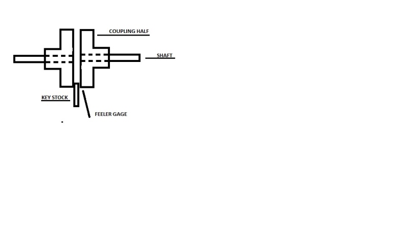
I am at wits end. I have a baler with an electric motor that drives a hydraulic pump. But. The Couplings keep slipping away from each other. Sometimes its the Motor side sometimes its the pump side. I have replaced Both Couplings and the buffer. Locktited the Set screws but it keeps happening. Any suggestions?
 
Replies continue below

Recommended for you

Do you have the correct fit between the motor shaft and coupling? It's going to be somewhere between 0 and 0.001" so it's tight. How is the angular misalignment of the pump amd motor. Angular misalignment can generate a sort of vibrating thrust against the coupling.

Is the coupling rated for the torque it is transmitting?
 
I would check for alignment issues first.
I love to hate balers.


Bill
--------------------
"Why not the best?"
Jimmy Carter
 
WE have it aligned to the best of our Ability. Looks STraight and Even. I am not sure if the Coupling is rated for this baler. We are using a Magnaloy M300 Series and its only a Medium Duty. This is an EXCEL 63 Horizontal Baler pulling some major Pressure, so It would seem a Heavy duty would be more in order. Plus ALOT of Forward and reverse. As far as tight. I measured the Shaft and it looks 1/2" to me but a 1 1/2 Coupler will not fit no way. So I'm using a 1 5/8. So now that I said that Out loud, Maybe the shaft is metric and I'm using the wrong ones completely. I just followed what came with the machine. Hmmm.
 
Yes, the coupling needs to fit tight on the shaft. Get the right one.
 
1 5/8" - 1 1/2" sure looks like a 1/8" misalignment despite what it looks like.

Bill
--------------------
"Why not the best?"
Jimmy Carter
 
Old school and often good enough; Snug an adjustable wrench onto the shaft. Remove the wrench without changing the setting and measure the gap between the jaws with a tape measure. Or check it against a known diameter shaft or drill bit..

Bill
--------------------
"Why not the best?"
Jimmy Carter
 
Whenever you are dealing with a Forward and Backward rotating motion, that is what is call "fully reversing torque" These applications are the most demanding of all coupling applications. Almost all couplings are rated for "continuous torque". So in many cases you need to add a service factor of 3 for fully reversing torque applications. In terms of slipping on the shaft, the same thing applies. Depending on shaft diameter(if using very small shaft, less than 3/4") you may find it impossible to put a fit on the hub/shaft that will withstand the fully reversing torque. Small shafts are very difficult to get fits to withstand fully reversing torques because the tolerances get so tight that you walk the line between functional use and impossible to assemble on the shaft. If you post the motor h.p. and speed rating as well as both shaft sizes I can recommend a solution for you.

When it comes to couplings we are always here to help.
 
OP said:
Plus ALOT of Forward and reverse.
Are you driving the pump in reverse?

Bill
--------------------
"Why not the best?"
Jimmy Carter
 
You don't need to measuree shaft. You can also look up the diameter with the frame size listed on the nameplate.
 
You post immediately made me think the pump is causing a torsional vibration that is then causing the couplings to shift. I would look at a coupling which allows more vibration damping as well as using taper lock coupling hubs. If it's not a very high HP I'd suggest using a tyre coupler. I don't know if there is another name besides brand specific names, but these look like a tire with the beads captured at each coupler flange. They can allow for lots of misalignment and absorb lots of vibration compared to many other couplers.
 
Yes, that's one of the brand names for that type of coupler. I posted that I didn't know a more appropriate generic name.
 
Got a photo of the shaft and of the coupling bore?

Sometimes there is a setscrew on the key and sometimes another setscrew on the shaft.

If you have a setscrew directly on the shaft, consider dimpling the shaft at the position the setscrew will engage.

=====================================
(2B)+(2B)' ?
 
OP said:
I measured the Shaft and it looks 1/2" to me but a 1 1/2 Coupler will not fit no way. So I'm using a 1 5/8. So now that I said that Out loud, Maybe the shaft is metric and I'm using the wrong ones completely. I just followed what came with the machine. Hmmm.
Not to disparage but if this is the best you can do for shaft size, how do you know if the shafts are aligned?
Here's an old school alignment procedure that may help:
Fix both coupling flanges on the shafts.
Leave the drive elements out of the coupling for now. Find something to use as a spacer between the coupling flanges.
Possibly a piece of key stock. You want about 40 or 40 thousands of an inch clearance between the spacer and the coupling flanges.
Now insert the spacer at one side of the couplings and measure the clearance with a set of feeler gauges.
Rotate the coupling halves about 15 or 20 degrees and recheck the clearances at the same place on the coupling halves. The clearances should be equal.
It helps to put a mark across the coupling flanges so as to always measure at the same place on the flanges as they are turned.


Bill
--------------------
"Why not the best?"
Jimmy Carter
 
coupling_c0j8j2.jpg


Bill
--------------------
"Why not the best?"
Jimmy Carter
 
Status
Not open for further replies.

Part and Inventory Search

Sponsor