Eng-Tips is the largest engineering community on the Internet

Intelligent Work Forums for Engineering Professionals

Cover Plate with Single Bolt

Status
Not open for further replies.

CDLD

Structural
May 20, 2020
209
1
16
CA
Good afternoon,

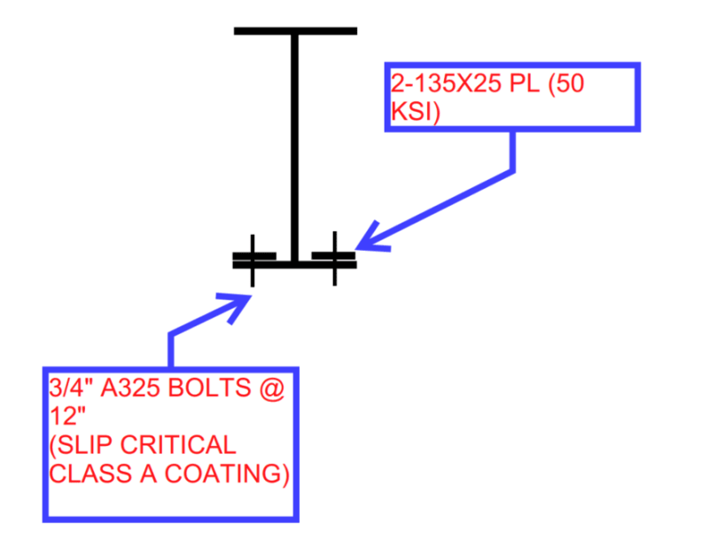
I have a situation where we are bolting cover plates to the topside of the bottom flange of an existing galvanized member.

I can satisfy the shear flow demand with one bolt at the center of each cover plate.

Do you foresee any stability issues with the single bolt arrangement?
Typically we would use a bottom plate with welds on each side.

Screenshot_2023-11-01_154134_y268ni.png


Thank you!
 
Replies continue below

Recommended for you

I assume the new plates are intended to help with flexure, so the load on the bolts would be parallel to the beam longitudinal axis. If so, then I don't think there's a stability or similar issue.

Depending on what you're trying to do, you might want to jack up the existing beam, install the new plates and bolts, and then release the jacks.
 
I don't think so.
The closest example I can find in the AISC manual is Figure 12-17 (13th edition). The added plates are above the top flange and below the bottom flange and extended the full width of the flange. There is a single row of bolts on each side of the web.
Seems with 2 separate plates the tension in the plate at the bolt would only be the width of the bolt and then radiate out to the edges between the bolts.

All I know is P/A and Mc/I
 
Do you mean a single ROW of bolts, or a SINGLE bolt? If the former, I'm ok with that. If the latter, how will any load ever get into your reinforcing plate?
 
271828 said:
I assume the new plates are intended to help with flexure
Correct. We have strong-axis bending only.
This got me thinking, would you change the fastening if there was weak-axis bending?
The plate would not be stressed uniformly for weak-axis bending.
edit [Need to think about this statement more (tomorrow)]
jayrod12 said:
Do you mean a single ROW of bolts, or a SINGLE bolt?
Single row of bolts (3/4" bolts @ 12" longitudinally).


Thanks for the validation gentleman (and ladies?), it's nice to get a second opinion every now and then.
 
If for composite action, slip critical connections have limited shear capacity.

-----*****-----
So strange to see the singularity approaching while the entire planet is rapidly turning into a hellscape. -John Coates

-Dik
 
CDLD -
The lower flange is presumably in tension? If so no issue.
If the lower flange is in compression, then there could be buckling issues via:
- inter rivet (bolt) buckling
- free edge buckling/crippling
Depends on loads and geometry.
 
Check for buckling, but those are pretty substantial BAR sections 1" thick with an r of about 0.3in... at 24" o/c, the kl/r is less than 100. In a pinch, you could likely use a k = 0.7. I don't think compression is a big thing. What is the size of the W section?

-----*****-----
So strange to see the singularity approaching while the entire planet is rapidly turning into a hellscape. -John Coates

-Dik
 
SWComposites said:
If the lower flange is in compression, then there could be buckling issues via:
- inter rivet (bolt) buckling
- free edge buckling/crippling
Depends on loads and geometry.
Bottom flange is in tension, though I agree with your checks if it were for a compression flange.

dik said:
If for composite action, slip critical connections have limited shear capacity.
Agree - they are good for about 8.4k / bolt in service loads.
At the ends of the member, we decreased bolt spacing to every 6".

dik said:
What is the size of the W section?
W27X146
 
Status
Not open for further replies.
Back
Top