Continue to Site

Eng-Tips is the largest engineering community on the Internet

Intelligent Work Forums for Engineering Professionals

  • Congratulations GregLocock on being selected by the Eng-Tips community for having the most helpful posts in the forums last week. Way to Go!

CPU vs VFO systems

Status
Not open for further replies.

akkamaan

Agricultural
Jun 20, 2010
110
We have 3 basic variable flow "ConstantPressure" systems in mobile hydraulics.
1. Constant Pressure, CP CC,(Closed Center) system
2. Constant Pressure Unloaded, CPU OC (Open Center) system
3. Load Sensing, LS system.
The reason I add the LS system to "constant pressure systems" is that LS uses the same pump and also pressure compensates the pump the same way as the CPU system. The difference is that the LS system uses a variable LS-signal from the actuator load, and the CPU system uses an orifice flow that the spool (initially) interrupts into a max pressure signal.

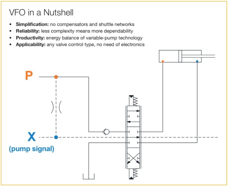
Now I have read this Parker explanation of its Variable Flow Open, VFO, center system. and it is explained in schematics to be identical with the CPU system, but the author Germano Franzoni states following on the last page
"VFO technology can be easily
combined with any load-sensing
(post- or pre-compensated) valve
as well as CPU (constant pressure
unloaded) valves."
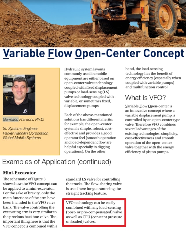
germano_parker_cpu_vfo_upliop.jpg


This indicates that his VFO system is different from a CPU system.
I have over the last year asked Parker via email and on Twitter about the specific difference between CPU and VFO.
My own images
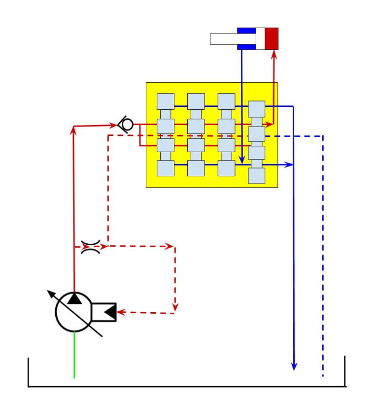
#1 unloaded
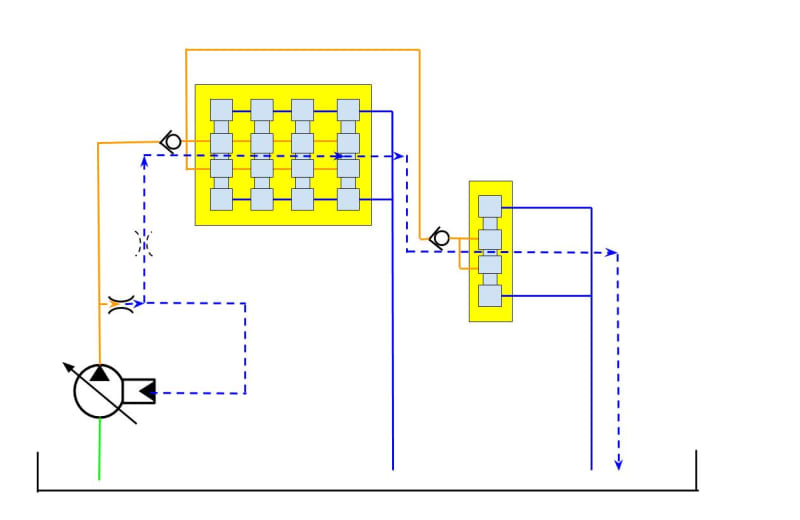
Pump_3_avlastad_seriekopplade_ventiler__f1pnkn.jpg

#2 loaded
Pump_2_p%C3%A5lastad_jmzran.jpg

Image 1 from Parker PDF
parker_vfo_cpu_hn210p.jpg

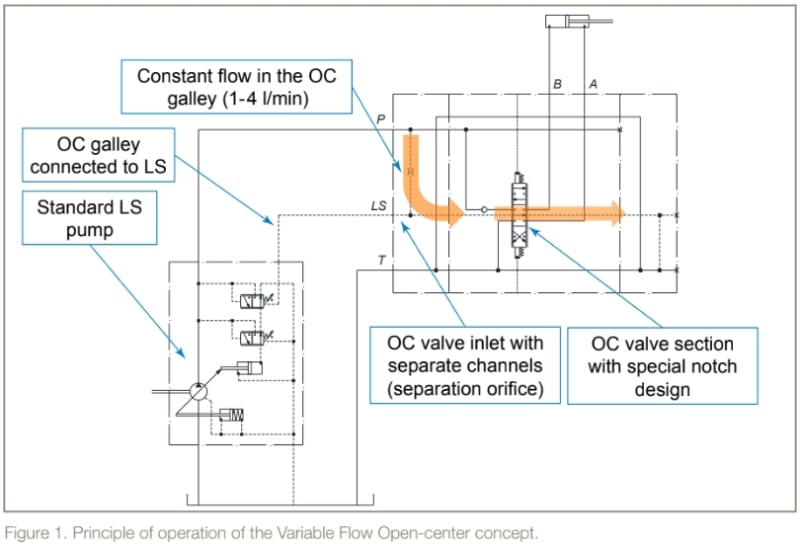
Image 2 from Parker PDF
parker_cpu_ylc4gr.jpg

Parker VariableFlowOpen center system PDF
Is there anyone here that can bring some light into this new "VFO" system term?
 
Replies continue below

Recommended for you

I have never seen or heard of the VFO system, but I'll offer my take from what you have posted. This looks like some kind of patent work-around or someone maybe trying to re-invent the wheel, at the least it's Parker marketing at it's finest. I don't see why this would be classified as an open center control valve, as all they are doing is allowing load sense pressure to bleed to tank when in neutral, which all load sense valves will have some kind of load sense pressure bleed-off feature.
The one thing that I see which is different is that this system can operate without the use of shuttle valves between the sections, which I guess should reduce the manufacturing cost of this valve. However, since the LS pressure isn't being sensed at the work port of the section, you won't get proportional flow/pressure from the hydraulic pump. The hydraulic pump will fully stroke and maintain the compensator pressure setting regardless of how the operator strokes the control valve. This would create a large pressure drop and wasted energy while the operator is feathering the controls, and with an excavator the operator is always feathering the controls. Maybe this valve is meant to be used as an auxiliary control valve that you can plumb in parallel to an existing load sense/closed center system, but short of that I am not sure what advantages this valve would offer over a conventional load sense directional control valve.
 
I don't see what I know as an open-center valve where in the valves off position the pressure port is connected to the tank port. What I see are all closed-center valves where both pressure and tank ports are blocked when the valves are centered. There is a constant flow through the valves galleys. I would not really call that open-center. The valve centered characteristic is what defines open or closed center.

Ted
 
All is just fine with the schematics above.
Problem solved.
The VFO system has the same schematic layout as the CPU system,
BUT
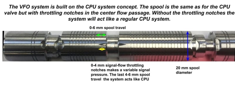
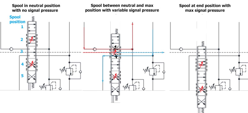
the VFO system has a special spool that allows throttling the signal flow that comes through the control orifice upstream of the control valve. According to an engineer at Parker office in Elk Groove Illinois, Jarmo H, the spool has special fine deep notches that throttle the signal-flow throughout the spool movement. That gives a variable signal pressure back to the pump compensator proportional to the spool position.
It is actually very simple since the can use the standard CPU directional valve pack and the same CPU spools that are just modified with this special notch.
The standard CPU system spool directly cut the entire signal control flow when spools initially move from the neutral position while. The modified VFO spool doesn't cut the entire signal flow until the spool reaches the end of its full stroke. At the end position the signal pressure is maxed out and so will the pump pressure be.
Just now the control orifice is a variable needle valve in the lab environment since the system hasn't been sold out on the market yet.
The original CPU orifice has a diameter of 0.7 mmm, this VFO system requires a slightly bigger signal flow to bet "throttable", so it's more equal to 1.0 mm diameter and that will make the control flow 1-4 l/min.
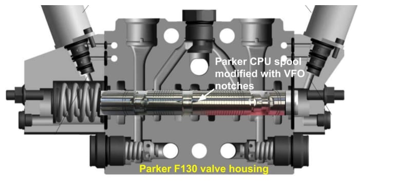
VFO_spool_notches_d9geqr.jpg

In this image, I have photoshopped the spool into the valve housing to show the proportions of the special notches
VFO_spool_in_F130_CPU_valve_housing_eua7vv.jpg
 
Hurtan_Albertan said:
I have never seen or heard of the VFO system, but I'll offer my take from what you have posted. This looks like some kind of patent work-around or someone maybe trying to re-invent the wheel, at the least it's Parker marketing at it's finest. I don't see why this would be classified as an open center control valve, as all they are doing is allowing load sense pressure to bleed to tank when in neutral, which all load sense valves will have some kind of load sense pressure bleed-off feature.
The one thing that I see which is different is that this system can operate without the use of shuttle valves between the sections, which I guess should reduce the manufacturing cost of this valve. However, since the LS pressure isn't being sensed at the work port of the section, you won't get proportional flow/pressure from the hydraulic pump. The hydraulic pump will fully stroke and maintain the compensator pressure setting regardless of how the operator strokes the control valve. This would create a large pressure drop and wasted energy while the operator is feathering the controls, and with an excavator the operator is always feathering the controls. Maybe this valve is meant to be used as an auxiliary control valve that you can plumb in parallel to an existing load sense/closed center system, but short of that I am not sure what advantages this valve would offer over a conventional load sense directional control valve.
hydtools said:
I don't see what I know as an open-center valve where in the valves off position the pressure port is connected to the tank port. What I see are all closed-center valves where both pressure and tank ports are blocked when the valves are centered. There is a constant flow through the valves galleys. I would not really call that open-center. The valve centered characteristic is what defines open or closed center.

The VFO system isn't a "Load-Sensing" system, it is more a "Spool Position Sensing" system.
I understand your comments about the definition of Open Center systems versus closed center systems.
Regular Load Sensing systems with pressure compensated variable pump usually doesn't have any flow leaking to the tank (I am talking about Parkers LS system with load signal copying valves in the spools).
A CPU system always has a control flow via an control orifice through an open center in the directional valve. The difference between a Constant Pressure Unloaded Open Center, CPU OC, system and a regular Constant Flow Open Center, CF OC, system is that the CPU system closes the center at the beginning of the spool stroke, and the CF fully closes the center at the end of the spool stroke.

A regular CP system doesn't have any control flow through the center and then is a fully Closed center system.

I know this is confusing and the industry mixes this up a lot. But it is pretty well understood in the mobile hydraulic industry.

The reason Parker has developed this VFO system is the take the efficiency pros from the variable flow CPU system and combine it with the "feel" pros from the CF system for the backhoe and excavator market. The excavator tradition is used to have a CF hydraulic system that lets the operator "feel" when the bucket hits resistance in the ground (like a sewer or a cable) by slowing down the motion. With a modern CPU or LS system, they don't get that same "feel".
With this VFO system, they will get that feeling, or at least something close to it.

CPU or LS systems will still be the to-go systems for hydraulic cranes in the logging machine industry and similar applications

Here is another schematic showing the five different VFO spool positions
variabelt_signaltryck_neutral_r%C3%B6d_strypning_vph5kv.jpg
 
I think it also has to do with efficiency. A constant pressure system is not very fuel efficient at low to medium loads.


CPU systems will still be the to-go systems for hydraulic cranes in the logging machine industry and similar applications? Really?
Name one manufacturer that is currently using CPU system for hydraulic cranes in the logging machine industry.
 
Jacc said:
I think it also has to do with efficiency. A constant pressure system is not very fuel efficient at low to medium loads.
It depends on what we compare with. An LS system where we run 2-3-4 high flow and low-pressure actuators simultaneously with 1 low flow and high-pressure actuator the efficiency gain with LS is almost eliminated because the pump pressure s determined by the highest load pressure. And since we operate a crane with several functions at the same time we might not get the "advertized" efficiency all the time

CPU systems will still be the to-go systems for hydraulic cranes in the logging machine industry and similar applications? Really?
Name one manufacturer that is currently using CPU system for hydraulic cranes in the logging machine industry.

I agree I used my words uncarefully and I could have canceled out CPU When it comes to logging equipment. My CPU mention was based on the fact that Parker Hannifin still are on the market with CPU systems with its valve P70, a valve that can be used for LS and constant flow as well. Scandinavian logging equipment manufacturers pioneered with LS in the 1980s. Parker Hannifin is the market-leading manufacturer och hydraulic systems to the Scandinavian manufacturers and they started the LS development when their mobile division was Monsun-Tison and later VOAC. Today they are all building LS systems. I am not so sure about the rest of the "primitive" world.

But for machines with harvester-heads, the LS system will need to be temporarily converted to CP(U) with a pressure loading valve while the harvester-head is operating.

LS works pretty much perfect today together with flow compensators on each valve section.

But there still areas where the system might need extra help. Overrunning loads and loads with no initial load pressure present like a swing or a grapple rotator. This can make the pump oscillate and make an erratic control. In these cases, if we don't use counterbalance valves and/or one-way check valves a CPU system works more consistently.
 
Status
Not open for further replies.

Part and Inventory Search

Sponsor