Eng-Tips is the largest engineering community on the Internet

Intelligent Work Forums for Engineering Professionals

  • Congratulations waross on being selected by the Tek-Tips community for having the most helpful posts in the forums last week. Way to Go!

Creasing/cross-breaking sheetmetal parts? 1

Status
Not open for further replies.

rossob

Mechanical
Jul 22, 2007
70
0
0
AU
Hi all,

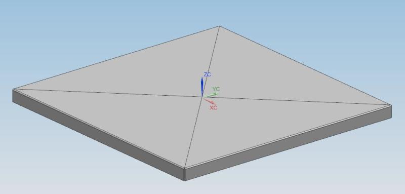
Wondering if it were at all possible to crease/cross-break a sheetmetal part, as per attached image, in NX9?
crease_qh2akh.jpg


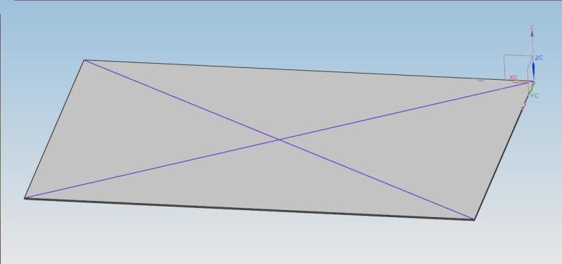
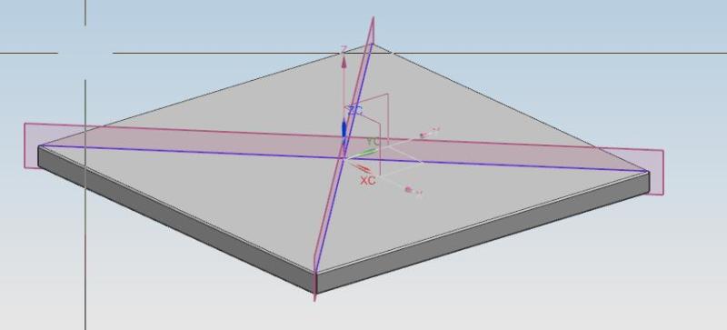
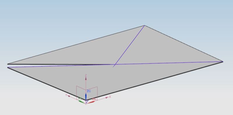
I can create a flat plate and draw a line/s. Using the bend command allows me to bend one side only. Attempting to bend the second line results in the plate being split, as follows:
split_z6vps4.jpg


At this stage, my work-around is purely to add some lines on the drawing view as an instruction to crease at those locations. Has anyone had any success in doing this a different way, or have any best practices they would like to share? Thanks in advance.

Regards,
Ross
 
Replies continue below

Recommended for you

I think you'll have to do it in Solid Modelling rather than sheetmetal with the flat pattern being purely the projection of the perimeter.

Khimani Mohiki
Design Engineer - PENSO Consulting Ltd
 
Hi Khimani,
I have managed to find a few ways of doing this.

The first is to create your sheetmetal part, then add a sketch to define the required crease/s. This sketch can then be added to the model reference set, so it shows up in a parent assembly, and then also added as additional curves to the flat pattern. This doesn't look great in a modelling context as you see sketch curves.

The second is a bit more long-winded, but looks much better.
1. Create the sheetmetal part, and add a sketch to define the required crease/s. Add some planes along those crease lines.
crease_geometry_hjx9a1.jpg


2. Extract the body and ensure "fix at current timestamp" is checked.
3. Divide the face using the newly created planes
divide_face_m53zk6.jpg

4. Create a flat pattern, using the required face of the extracted body as the Upward face
5. Add the edges created by the Divide face feature as additional curves
6. Create drawing view/s, ensure that smooth edges is turned on. Callouts to the crease lines will need to be manually added
flat_pattern_s86bpu.jpg


Ross
NX9.0.3.4
TC V10.1.2.2
 
Status
Not open for further replies.
Back
Top