Continue to Site

Eng-Tips is the largest engineering community on the Internet

Intelligent Work Forums for Engineering Professionals

  • Congratulations KootK on being selected by the Eng-Tips community for having the most helpful posts in the forums last week. Way to Go!

Create a Surface Mesh from Tet Solids ("Skinning")

Status
Not open for further replies.

RealSaladsamurai

Mechanical
Apr 11, 2012
72
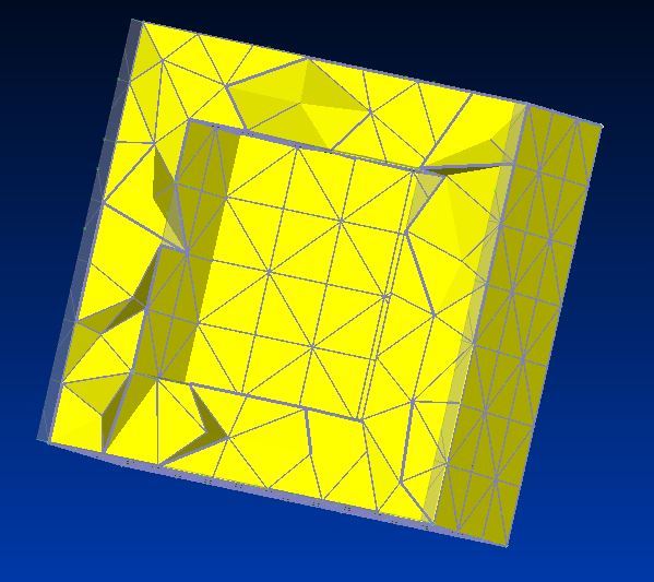
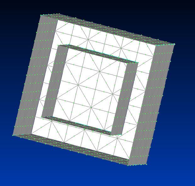
I have heard Patran users refer to this as skinning a mesh, but I cannot seem to find the Femap equivalent (if one exists). I have a simple example of what I am trying to accomplish. I have a cube, which has a smaller cube removed from the center so that there is an empty volume inside (see images). In the images I am showing a section cut through the center of the cube. Note that in the first image, it looks like 2 surface meshes, but it is really a solid mesh; that is the way Femap renders a section cut, so I show a highlighted image to help clarify.

I want to do the 2 following things:

1) Create a surface mesh that is identical to the free faces of the inner surface of the cube.

2) Take that "matched" surface mesh and "fill" it in with solid tet elements.

Can anyone offer some guidance on how to accomplish this?

cube_oi5dmi.jpg
cube2_svs4rr.jpg


________________________
FEMAP v11.1.0
MSC Nastran v2013
 
Replies continue below

Recommended for you

Hello!,
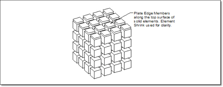
Yes, you can do it with command "MESH > EDGE MEMBERS" that allow to create planar elements on the free faces of solid elements. This command provides a convenient way for framing plate or beam structures with beam or other line elements, and for paving the surface of solid structures with plates or membranes.

You must select the elements that you want to frame using the standard entity selection dialog box. You do not have to specify one contiguous group of elements. FEMAP uses the same logic that it uses for a free edge/face plot to determine the locations where elements will be created. In fact, you can use this method to make a preliminary check. Just select the elements to be “framed” into a group, select the group for display and choose a free edge or face plot. The edges/faces you see will create elements.

If you select solid elements, planar edge members will be created. You should not select both planar and solid ele­ments in the same command.

edge-members_luth3z.png


Once you have the "skin" created using 2-D plot planar elements, then you can use command "Mesh > Geometry > Solids from Elements..." and select the planar ele­ments enclosing a volume to create a 3-D solid TET10 mesh.

Best regards,
Blas.


~~~~~~~~~~~~~~~~~~~~~~
Blas Molero Hidalgo
Ingeniero Industrial
Director

IBERISA
48004 BILBAO (SPAIN)
WEB: Blog de FEMAP & NX Nastran:
 
Hi Blas - This looks like it is exactly what I am looking for. I will test it tomorrow at work. Thank you!

________________________
FEMAP v11.1.0
MSC Nastran v2013
 
I guess I don't fully understand how to use this command. When I select solid elements and assign a plate property, it then asks me to "Select Nodes to Limit Free Edges or Faces" .... I don't really know what it wants? I was hoping that this method could pick out the free faces automatically, but it seems it cannot. I have to go in a pick specific nodes to limit face element creation. I would think that I should only have to pick 1 element and 1 free face and the algorithm should be able to pick all connect free faces.

________________________
FEMAP v11.1.0
MSC Nastran v2013
 
Hello!,
Select all element and all nodes and you will have "coated" all your free faces elements with 2-D elements. The node selection is to limit the extension of the coating.
Best regards,
Blas.

~~~~~~~~~~~~~~~~~~~~~~
Blas Molero Hidalgo
Ingeniero Industrial
Director

IBERISA
48004 BILBAO (SPAIN)
WEB: Blog de FEMAP & NX Nastran:
 
Hi Blas! Thank you again for your help! It is always appreciated.

________________________
FEMAP v11.1.0
MSC Nastran v2013
 
Status
Not open for further replies.

Part and Inventory Search

Sponsor