Continue to Site

Eng-Tips is the largest engineering community on the Internet

Intelligent Work Forums for Engineering Professionals

  • Congratulations KootK on being selected by the Eng-Tips community for having the most helpful posts in the forums last week. Way to Go!

Creating a curve by equation 6

Status
Not open for further replies.

Columb

Mechanical
Sep 18, 2008
7
Hello

How should I create a curve by equation?
The equation is the involute equation:
x=r(cos(t)+t*sin(t))
y=r(sin(t)-t*cos(t))
r and t are known and I can get the points(x,y)but I need to draw the curve.

Thanks
Columb

Columb
 
Replies continue below

Recommended for you

Create laws using your equations, then use parallel curve to apply the law to a line (requires GSD license). There is a good example of this in the documentation
 
EquaCurve_04.jpg


Constructing a curve from an equation is something I do using the Excel file method - it's very fast, and it's easy to edit the code and re-run it. In the Help documentation a search for "Creating Elements from an External File" describes the process. An in-depth knowledge of VB is not really necessary - even TurboBasic will run in the macro - with slight alteration.

The equation given is obviously for a planar curve - there is no Z-value mentioned. So, in the macro, Z must be given a value - in this case, of zero.

EquaCurve_05.jpg


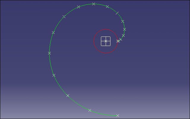
This is what the involute looks like (with z = 0). The parameter (t) was interrogated for 0<t<2Pi (one rotation). The radius (r) was given an arbitary value of 100, and the number of points calculated was kept low for this excercise, but up to 500 can be used.

The x,y and z values of the curve have been calculted in a VBA macro - to create a Excel file that can be imported into V5. The simplistic code is the active loop that calculates the points. (The rest of the macro has been omitted for clarity)

Code:
                        		Cells(c, 1) = "StartCurve"
                        For t = 0 To (2 * Pi) Step (Pi / 8)
                            	x = r * (Cos(t) + t * Sin(t))
                            	y = r * (Sin(t) - t * Cos(t))
                            	z = 0
                            c = c + 1
                        		Cells(c, 1) = x
                        		Cells(c, 2) = y
                        		Cells(c, 3) = z
                        Next t
                        		Cells(c + 1, 1) = "EndCurve"
End Sub
				Cells(c + 2, 1) = "End"

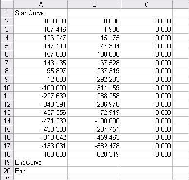
When the Excel macro is up and running properly it will create an Excel sheet - see below. It must be correct or it will not send the point data into Catia. The Help documentation explains how to run the whole process - if points only are required the Option 1 is used in the Main Macro; if the curve is wanted as well, then use Option 2. (Option 3 is for creating a surface)

The format of the Excel sheet below is for creating a curve.

EquaCurve_06.jpg
 
Thanks PeterGuy for replay but the fog-law works with two parameters only, I have 3 parameters: x,y and angle t.

I'll try what Kapitan said.
Thanks Kapitan for your answer.It looks great.


Columb
 
Hello,

What Kapitan is saying is that you do not create the curve from equation in CATIA. Using Kapitan's script,you create points from the equation in EXCEL.

Then bring those points and build curve in CATIA with the script from the online doc.

Eric N.
indocti discant et ament meminisse periti
 
Yes it's true Itsmyjob ,the points are calculated in EXCEL and a spline through these points are made in CATIA.It'd be nice to have a function like 'spline/curve from equation' as UG or ProE has.
I'm still thinking about the law procedure why I can't use 3 parameters...


Columb
 
Hi

Finally I succeeded to make the involute in Catia.
I did one law (law1)for the x formula:
x=r(cos(t)+t*sin(t))
and than another law (law2)for the y formula
y=r(sin(t)-t*cos(t))

Using parallel curve to apply the law to a line (with advanced option) and indicate the law#1 I created a curve in XY plan then I did the other projection in the XZ plan in the same way using law#2
The next step is to combine these new projections from xy and xz planes and get a new 3D curve.
Finally project this 3D curve on the other plane yz and get the 2D involute.

Regards


Columb
 
Hi again

I'm stupid, I just realized the same method is in doc at:
Creating a Parameterized Curve
but has a strange name for a curve from equation.

Regards

Columb
 
I think I mentioned there was an example in the docs
 
Yes PeterGuy you mentioned before but I couldn't find this example first.I didn't expect to name this in doc "Creating a Parameterized Curve".
Anyway I gave you a star.


Regards,

Columb
 
Thank you you are a very nice man. I usually try to mention any odd terminology as DS like to make things up , but I was pressed for time so gave a terse answer
 
yep a star for you... we don't see them often anymore.

I still have to go in the online doc and look at this.

May be I'll document it with pictures if nobody does it before I find some time.

Eric N.
indocti discant et ament meminisse periti
 
EquaCurve_08.jpg


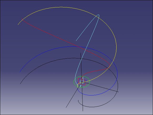
It seems to me that this particular Law method of making the involute of a circle is unnecessarily complicated - and not the best way of constructing an involute (in this case, of a circle) in V5. What appears to be happening is that two component plane curves - x(t) and y(t), shown as red and light-blue - are being constructed, then combined to form a helical-type space curve (x,y,z), in yellow. This is then projected, or effectively collapsed, on to a plane (blue) to make the involute (x,y). Why go from 2D to 3D and back to 2D - when the calcs can be done direct in 3-space? Is it because the Excel-macro method is using a tool that's outside Catia?

The black involute shown below the blue one is an Excel-macro one - both curves are identical - but one is far simpler to do than the other.

The construction of a circle involute is simple - after all the curve is, in effect, the locus of the end of a piece of string being unwound from a circular drum - and the parameter 't' is the angle of unwinding - at the point of tangency. Ignoring 'z' - as it's zero, this involute has 2 variables (x,y) - each of which is a different function of a single parameter (t). (This involute is so elementary that the normal at any point on the curve can be found by constructing a single line - from that point so that it's a tangent to the approaching side of the circle - rather than the retreating side.)

EquaCurve_11.jpg

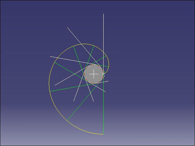
Involute of a Circle - by kinematic construction

But there is another, and very different, approach - if you have the Kinematics licence then there is probably no faster way of creating a pure involute than rolling a line around a circle - and tracing the end point of the line. An involute is one of the so-called 'classic' curves that can be described by a mechanism. (Even a Bezier curve, using control points, can be driven from a set of simultaneous mechanisms - there's no practical point in actually doing it, and it gets complicated - it's just interesting...and it would make a good, advanced, kinematic training exercise.)

The picture above shows a circle of radius (r) - with a line of length (2 * Pi * r) being rolled around its circumference. The involute is the yellow curve. A line of this length will obviously rotate one revolution. A trace of the other end of the line will give the opposite handed curve.

If, for some reason, the curve must be constructed completely within Catia, with a Law, (ie not with Excel), then here's a link to how to go about it - but I certainly wouldn't do all this to get an involute. If I'm going to make plane curves, space curves or surfaces that can be defined by either Cartesian, parametric or polar equations, I wouldn't hesitate to go the Excel way, and if that didn't give a satisfactory result then I'd think about some other method.

This subject has also become a lengthy thread here, since it began earlier this year.
 
A star for you Kapitan, as always a master of explanations. I have to learn from your posts how to explain things....

Regards
Fernando
 
Whilst being complex the law method does give you something the other methods don't, which is the associativity of the result to the input geometry. This is an important criteria if you are building template/standard parts or powercopies/UDF's but a lot less important in a large number of design scenarios. We should select the method that gives not only the result we require but also the behaviour during change.
 
Hello,

I agree with PeterGuy about associativity.The radius would suffer most changes for sure and a new involute is updated immediately.

Thanks Kapitan for explanation and the links.
Definitely you are the master of explanations.


Regards

Columb
 
Status
Not open for further replies.

Part and Inventory Search

Sponsor