Eng-Tips is the largest engineering community on the Internet

Intelligent Work Forums for Engineering Professionals

  • Congratulations waross on being selected by the Tek-Tips community for having the most helpful posts in the forums last week. Way to Go!

Creating floor with a slope in Abaqus 1

Status
Not open for further replies.

rte4563

Mechanical
Sep 28, 2022
40
0
0
NO
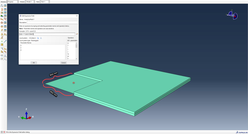
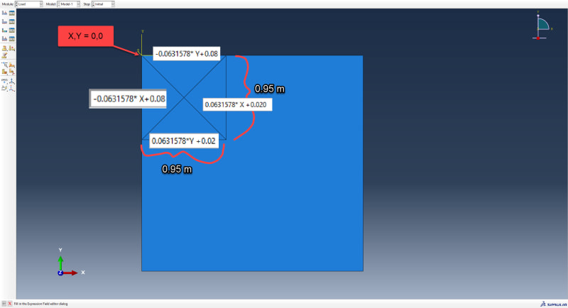
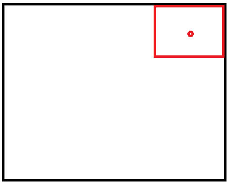
I wanna model a bottom floor with a thickness of 100 mm everywhere besides when we get to the red part. Here it will slope downwards to a minimum thickness of 70mm. So from the edge of the red box to the red point the structure will go down about 30 mm.

How could I go about doing this the easiest way? Shell extrusion? Shell planar? I also have 4 walls and roof I need to attach to this concrete floor.

The ground with a thickness of 100 mm, but slopes downwards to 70mm from edge of the red box.
1_txurys.jpg
 
Replies continue below

Recommended for you

You can define variable thickness for shell elements. Based on either element or nodal distribution. In both cases, analytical and discrete field definitions can be used.
 
Can I then use for example shell extrusion? Should I model two seperate parts, one with slope and a big one without then put them together? Or can I partition one part, and put one section to have varying thickness and one constant? Meaning two section definitions for one part.
 
If the geometry itself is flat, you can use the planar shell option to create it. You don't have to model multiple parts, one will be sufficient and shell thickness will be assigned on the mesh level. However, a partition separating the region with constant thickness from the one with variable thickness may help.
 
This is what Ive defined; I am not sure what the expression needs to look like if I want it to be for example 100 mm thick everywhere except in the corner where it gradually slopes down to 70 mm. Do I need to define a local coordinate axis at the red point where the height will be 70 mm, and then have it increase 0.95x = 0.03 where x=0.03157, so the expression would simply be Y*0.03157?

1_hqukhl.jpg
 
Basically, Abaqus will evaluate the specified expression (defined in terms of global or local coordinates) and use its result as a shell thickness at a given location. So, for example, the expression 0.2*X will result in a thickness of 2 for locations with an X coordinate equal to 10. You can check the correctness of the variable thickness definition by rendering shell thickness in the Visualization module and/or checking the STH output variable which can be added to field output requests.
 
Is there anything that looks wrong to you here? Ive made 4 analytical fields. I split into 4 "pizzas" with each its own analytical field to define thickness. I want it to be 50mm in the middle, where the two diagonal lines cross, and 80mm at the edges.
2_so1xli.jpg

Error message:
3_le8asq.jpg
 
I can't see the axes well but if the origin of that local CSYS is located in the top right corner then the coordinates substituted to some expressions might be negative. You can check this using the Query --> Point/Node and selecting local CSYS for this tool. Then pick the points to see their coordinates in local system.
 
Status
Not open for further replies.
Back
Top