DavidMcArthur
Mechanical
Hello all,
I am trying to create identical meshes on 2 opposing and parallel faces of a part (show below with red circles identifying example of opposite faces)
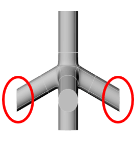
I need the nodes of the (linear tetrahedral) elements to be lined up really well (to within some small tolerance that I can set myself). I will then use a plugin to apply constraint equations between the pairs of nodes that requires them to have the same coordinates (excluding the coordinate in which the faces are separated).
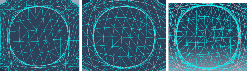
So far I have tried to fiddle with different mesh controls, seeding edges, structural vs free mesh etc. I then found out that you can edit the coordinates of mesh nodes in Abaqus. I have tried to write a python script to do this (manually would be too long as I want to do this with different geometries too). The python script is not behaving exactly as I hoped (I have attached the script and pasted the section of code below). As you can see, the meshes are very different. I can also see when I print the coordinates of all the nodes that they are not right. In the code, I have specified that I should change the coordinates of the node on face 2 to that of the closest node on face 1. If I don't do this, the nodes are pulled all over the place - it might match the coordinates of 2 nodes on opposite corners of the faces for example.
I have put a wetransfer link of my files here: If anyone wants to look.
Any help would be much appreciated. If there is a better more simple approach that would be great. Maybe there is some other software that can do this more easily too? I know of meshlab but I am not familiar with all the features.
Thank you all,
David
I am trying to create identical meshes on 2 opposing and parallel faces of a part (show below with red circles identifying example of opposite faces)
I need the nodes of the (linear tetrahedral) elements to be lined up really well (to within some small tolerance that I can set myself). I will then use a plugin to apply constraint equations between the pairs of nodes that requires them to have the same coordinates (excluding the coordinate in which the faces are separated).
So far I have tried to fiddle with different mesh controls, seeding edges, structural vs free mesh etc. I then found out that you can edit the coordinates of mesh nodes in Abaqus. I have tried to write a python script to do this (manually would be too long as I want to do this with different geometries too). The python script is not behaving exactly as I hoped (I have attached the script and pasted the section of code below). As you can see, the meshes are very different. I can also see when I print the coordinates of all the nodes that they are not right. In the code, I have specified that I should change the coordinates of the node on face 2 to that of the closest node on face 1. If I don't do this, the nodes are pulled all over the place - it might match the coordinates of 2 nodes on opposite corners of the faces for example.
I have put a wetransfer link of my files here: If anyone wants to look.
Any help would be much appreciated. If there is a better more simple approach that would be great. Maybe there is some other software that can do this more easily too? I know of meshlab but I am not familiar with all the features.
Thank you all,
David
Python:
#Python Code for trying to match coordinates of nodes on opposing faces
#
#generate mesh
#
mdb.models['Model-1'].parts['unit cell'].generateMesh()
#
#Edit Node Coordinates
#
#Collect Nodes on Faces
Nodes_1=mdb.models['Model-1'].parts['unit cell'].nodes.getByBoundingBox(-100,7.49999,-100,100,7.50001,100)
Nodes_2=mdb.models['Model-1'].parts['unit cell'].nodes.getByBoundingBox(-100,4.49999,-100,100,4.50001,100)
x_coordinate_list_1=[]
x_coordinate_list_2=[]
for i in range(0, len(Nodes_1)-1):
    current_node=Nodes_1[i]
    current_node_2=Nodes_2[i]
    x_coordinate=current_node.coordinates[0] #gather x and z coordinates on face 1
    z_coordinate=current_node.coordinates[2]
    distance=[]
    #Find closest node on face 2 to node i on face 1
    for j in range(0, len(Nodes_2)-1):
        distance.append(sqrt(((x_coordinate-x_coordinate_2)**2)+((z_coordinate-z_coordinate_2)**2)))
        min_distance = min(distance)
        index=distance.index(min_distance)
    current_node_2=Nodes_2[index]
    #Edit x and z coordinates of node on face 2 to match node on face 1
    mdb.meshEditOptions.setValues(enableUndo=True, maxUndoCacheElements=0.5)
    mdb.models['Model-1'].parts['unit cell'].editNode(coordinate1=x_coordinate, coordinate3=z_coordinate, nodes=
        current_node_2,
        projectToGeometry=ON)