Continue to Site

Eng-Tips is the largest engineering community on the Internet

Intelligent Work Forums for Engineering Professionals

  • Congratulations KootK on being selected by the Eng-Tips community for having the most helpful posts in the forums last week. Way to Go!

Creo Toroidal bend feature alternative in NX

Status
Not open for further replies.

Krishna.k

New member
Jun 14, 2019
7
Hello,

I have a Creo parametric model, Which I am converting to NX parametric model. I had an issue while converting toroidal bend feature in Creo to NX.

In Creo, Toroidal bend feature was created using flowing parameters.
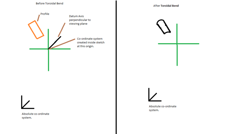
Toroidal_bend_fnl94g.png


As you see in the above picture, Rectangle was bent about an axis (used as BEND AXIS in Toroidal bend feature) which is not passing thru the absolute coordinate system.

on the right side of picture you can see the output of toroidal bend feature( "Preserve length in angular direction" option in Toroidal feature dialog is turned on so the distance from points on the curves to the plane of the profile section is maintained along the angular direction).

Please see this link for Toroidal feature documentation:
To reproduce this in NX, I tried to use Global shaping by curves feature. But I was not able to understand how to create Base curve and control curve to replicate this geometry.

Could you please help me to solve this problem.

Thanks & Regards,
Krishna
 
Replies continue below

Recommended for you

Hello Didier Psaltopoulos,

Thanks for the quick response :). I am sorry, I can't upload step file but I can give some more details.

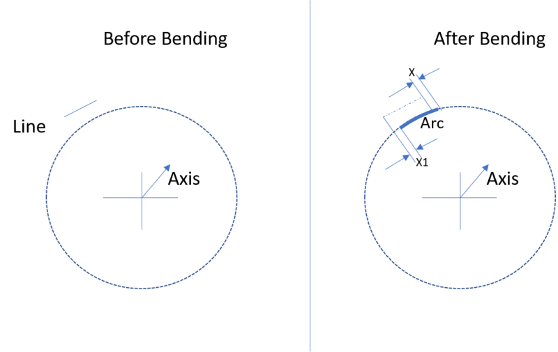
Tor1_drmutp.png


As you see in the above image if I have a straight line and Bent it about an axis Toroidal bend option is doing following things.

1) Converting line into arc (if it is a spline then Creo is using some different method and calculating creating new spline).
2) Moving end points of line to new location(If it is a surface then Creo is also scaling geometry).

I want to replicate same behavior in NX 12. Could you please help me with this.

Thanks & Regards,
Krishna.
 
Hello Didier Psaltopoulos,

Thanks for the reply. I think, Project curve is the good option if I have only one curve and I know the information about dotted circle, But Creo is computing the dotted circle (based on datum axis) and moving line to new points and converting into an arc. I apologies for not making this clear in my earlier post. I searched on YouTube to find some video but couldn't able to find video which describes current scenario, Here is a short video explaining about Toroidal bend .

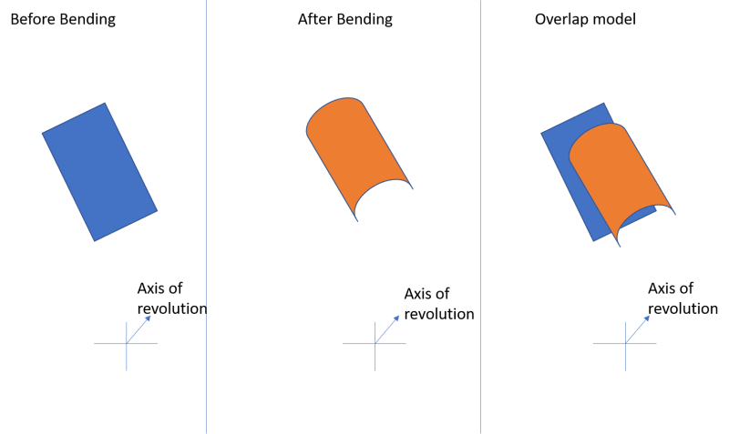
Picture1_su86fc.png


I only have a 2d surface not a solid, As per above picture if I take rectangle and bent about an axis it is giving new geometry as per the center image.

Could you please let me know how I can do this?

Thanks & Regards,
Krishna
 
Hello Thomas,

Thanks for the reply. I tried to use global shaping by curves, But I am not sure how to define base curve and control curve to replicate this behavior.

Could you please help me with this?

Thanks,
Krishna
 
Hi Krishna,

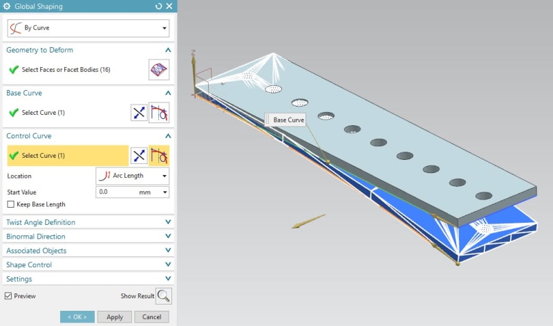
OK, I have understand with the video. Find below the explanation of base curve and find attached an example

Global_Shaping_By_Curve_mta46j.jpg


I hope this help


Regards
Didier Psaltopoulos
 
Hello Didier Psaltopoulos,

Thanks for the reply. I tried to define straight line (created line at the top of rectangle) as a base curve and arc (whose center is passing thru the datum axis) as a control curve. But that didn't give the results as expected. As per as I understand Global shaping by curves calculate the difference between two curve equations and bend the geometry. In Creo, only Profile, datum axis and coordinate system are given as input and output geometry is scaled and type of curves are also changed. I am not able to understand how to create a Base and control geometry which gives this output.

Thanks,
Krishna.
 
just try and try and try...
But maybe it's just one simple thing: You should use option "Keep Base Length" in Control Curve group.
There is also a lot of freedom for definition of the start point.
Base and Control Geometry is defined in Didiers example in Sketch (3): a straight line as Base and the Arc as Control.
 
Hello Thomas,

I tried so many ways but still not able to achieve this mathematical condition "Distance from points on the curves to the plane of the profile section is maintained along the angular direction". It seems I need to generate a new curve based on equations 😉 and use that as a base and control curve (For that first I need to know how Toroidal bend is calculating new points).

Thanks & Regards,
Krishna.
 
Status
Not open for further replies.

Part and Inventory Search

Sponsor